 |
 |
|
 |
|
 |
|  |
|  |
|
 |
|
 |
|  |
|  |
|
 |
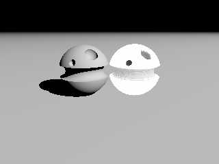
I tried a very crude implementation of my crevice grime idea (p.g) to see how it
would work in general. The object on the left is my base object. On the right
is my crevice results.
For this I am basically tracing a regular set of points around my object. I
then use tha point and normal found to run a series of traces at some angle from
the normal rotated around the normal (in this case I am using 32 traces at 75
degrees). I then check for intersection and distance to intersection for all
traces and then place a sphere on the surface at that location that is coloured
based on the average distance to intersections.
Very crude, but it appears to work somewhat, other than I would have liked to
colour my object directly rather than the little spheres. I am also using a
regular spherical array of traces from the center of the base object.
Perhaps one day I will get into the internal code and see if it's possible to
code internally.
-tgq
Post a reply to this message
Attachments:
Download 'trace1.jpg' (34 KB)
Preview of image 'trace1.jpg'

|
 |
|  |
|  |
|
 |
|
 |
|  |
|  |
|
 |
Am 13.03.2011 16:20, schrieb Trevor G Quayle:
> For this I am basically tracing a regular set of points around my object. I
> then use tha point and normal found to run a series of traces at some angle from
> the normal rotated around the normal (in this case I am using 32 traces at 75
> degrees). I then check for intersection and distance to intersection for all
> traces and then place a sphere on the surface at that location that is coloured
> based on the average distance to intersections.
What kind of average are you using?
Radiosity is using a harmonic mean (the inverse of the arithmetic mean
of the inverse values) for "closeness" computations, so that very far
distances don't dominate over the more interesting small distances.
Post a reply to this message
|
 |
|  |
|  |
|
 |
|
 |
|  |
|  |
|
 |
clipka <ano### [at] anonymous org> wrote:
> Am 13.03.2011 16:20, schrieb Trevor G Quayle:
>
> > For this I am basically tracing a regular set of points around my object. I
> > then use tha point and normal found to run a series of traces at some angle from
> > the normal rotated around the normal (in this case I am using 32 traces at 75
> > degrees). I then check for intersection and distance to intersection for all
> > traces and then place a sphere on the surface at that location that is coloured
> > based on the average distance to intersections.
>
> What kind of average are you using?
>
> Radiosity is using a harmonic mean (the inverse of the arithmetic mean
> of the inverse values) for "closeness" computations, so that very far
> distances don't dominate over the more interesting small distances.
Actually at present I was using and inverse function similar to the light
attenuation function.
pigment = (1-1/(1+adist))^10
This way far distances get diminished to near zero, and close distances get
weighted up to a value of 1. I will probably look at some other mean functions.
-tgq org> wrote:
> Am 13.03.2011 16:20, schrieb Trevor G Quayle:
>
> > For this I am basically tracing a regular set of points around my object. I
> > then use tha point and normal found to run a series of traces at some angle from
> > the normal rotated around the normal (in this case I am using 32 traces at 75
> > degrees). I then check for intersection and distance to intersection for all
> > traces and then place a sphere on the surface at that location that is coloured
> > based on the average distance to intersections.
>
> What kind of average are you using?
>
> Radiosity is using a harmonic mean (the inverse of the arithmetic mean
> of the inverse values) for "closeness" computations, so that very far
> distances don't dominate over the more interesting small distances.
Actually at present I was using and inverse function similar to the light
attenuation function.
pigment = (1-1/(1+adist))^10
This way far distances get diminished to near zero, and close distances get
weighted up to a value of 1. I will probably look at some other mean functions.
-tgq
Post a reply to this message
|
 |
|  |
|  |
|
 |
|
 |
|  |
|  |
|
 |
I have done some adjustments to my testing. I reverted to using a
pseudo-raytrace method for sampling: a square grid of traces from the camera to
the object. This gives much more effective coverage and ignores unseen surfaces
(not good for reflections yet).
I also tried out the harmonic mean approach to the colouring,as per clipka's
suggestion, and it looks ok at present. The only problem I foresee with it is
that it is not bounded by 1, however this may work out favourably by truncating
at 1, which would mean any value above 1 has zero effect.
This run uses a normal offset of 60deg, with 32 rotated samples. It coulred by
a direct harmonic mean of standardized distances (distances are standardized by
len/D where D=40, note the main sphere is 80 diameter).
I may still look at alternate distance weighting options such as inverse power
(1/2^x)
-tgq
Post a reply to this message
Attachments:
Download 'trace1.jpg' (21 KB)
Preview of image 'trace1.jpg'

|
 |
|  |
|  |
|
 |
|
 |
|  |
|  |
|
 |
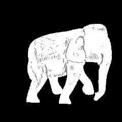
Had a bit of an error in how I was handling my harmonic mean function that I
fixed.
Here is a run on a real mesh, and it looks like there may some potential.
For scale, the elephant mesh is approximately 240x220x110. I have run a 500x500
sampling grid over a ~350x350 square. Note:I am using a square that uses the
diagonal corner length of the mesh bounding box, so it tends to end up larger
than it needs to be, but this just easily ensures that I am sampling the whole
object without having to sample the whole image/scene.
The other settings I used were:
normal angle = 75deg;
normal samples = 24;
standardized depth for harmonic mean = 10
-tgq
Post a reply to this message
Attachments:
Download 'trace2.jpg' (77 KB)
Preview of image 'trace2.jpg'

|
 |
|  |
|  |
|
 |
|
 |
|  |
|  |
|
 |
"Trevor G Quayle" <Tin### [at] hotmail com> wrote:
> Had a bit of an error in how I was handling my harmonic mean function that I
> fixed.
>
> Here is a run on a real mesh, and it looks like there may some potential.
>
> For scale, the elephant mesh is approximately 240x220x110. I have run a 500x500
> sampling grid over a ~350x350 square. Note:I am using a square that uses the
> diagonal corner length of the mesh bounding box, so it tends to end up larger
> than it needs to be, but this just easily ensures that I am sampling the whole
> object without having to sample the whole image/scene.
>
> The other settings I used were:
> normal angle = 75deg;
> normal samples = 24;
> standardized depth for harmonic mean = 10
>
> -tgq
This looks very promising, Trevor.
How's it look with the elephant turned y*45, and with some sort of shading?
(i.e., other than the white and grime). Just wondering if the occlusion still
works at some arbitrary angle to the camera...
-------------------------------------------------
www.McGregorFineArt.com com> wrote:
> Had a bit of an error in how I was handling my harmonic mean function that I
> fixed.
>
> Here is a run on a real mesh, and it looks like there may some potential.
>
> For scale, the elephant mesh is approximately 240x220x110. I have run a 500x500
> sampling grid over a ~350x350 square. Note:I am using a square that uses the
> diagonal corner length of the mesh bounding box, so it tends to end up larger
> than it needs to be, but this just easily ensures that I am sampling the whole
> object without having to sample the whole image/scene.
>
> The other settings I used were:
> normal angle = 75deg;
> normal samples = 24;
> standardized depth for harmonic mean = 10
>
> -tgq
This looks very promising, Trevor.
How's it look with the elephant turned y*45, and with some sort of shading?
(i.e., other than the white and grime). Just wondering if the occlusion still
works at some arbitrary angle to the camera...
-------------------------------------------------
www.McGregorFineArt.com
Post a reply to this message
|
 |
|  |
|  |
|
 |
|
 |
|  |
|  |
|
 |
"Robert McGregor" <rob### [at] mcgregorfineart com> wrote:
> This looks very promising, Trevor.
>
> How's it look with the elephant turned y*45, and with some sort of shading?
> (i.e., other than the white and grime). Just wondering if the occlusion still
> works at some arbitrary angle to the camera...
Thanks. It should work at any angle, as I am basically tracing rays directly
from the camera itself to only test the visible parts. Right now, the way it is
set up, if I shoot rays from a different location than the camera, you would se
where it is not test (backside) same with if I had reflections. I am just
using a faked raytrace method for testing purposes.
What I would intend to do is try to find a way to implement in the code itself
where it would use the traced rays themselves (similar to AO).
Shading isn't properly implemented at the moment either, as I haven't figured
out how to implement the results as a pigment, so right now it is just tiny
coloured shperes, though I do intersect them with the base object to try to
maintain the surface somewhat.
It really isn't what I would classify as occlusion: I am tracing rays from the
surface of the object at a given angle from the normal and testing for self
intersection.
I still have lots of things to test and work out (not to mention trying to
figure out POV compiling perhaps at some point in time).
One thing I am thinking about trying is adaptive subsampling.
-tgq com> wrote:
> This looks very promising, Trevor.
>
> How's it look with the elephant turned y*45, and with some sort of shading?
> (i.e., other than the white and grime). Just wondering if the occlusion still
> works at some arbitrary angle to the camera...
Thanks. It should work at any angle, as I am basically tracing rays directly
from the camera itself to only test the visible parts. Right now, the way it is
set up, if I shoot rays from a different location than the camera, you would se
where it is not test (backside) same with if I had reflections. I am just
using a faked raytrace method for testing purposes.
What I would intend to do is try to find a way to implement in the code itself
where it would use the traced rays themselves (similar to AO).
Shading isn't properly implemented at the moment either, as I haven't figured
out how to implement the results as a pigment, so right now it is just tiny
coloured shperes, though I do intersect them with the base object to try to
maintain the surface somewhat.
It really isn't what I would classify as occlusion: I am tracing rays from the
surface of the object at a given angle from the normal and testing for self
intersection.
I still have lots of things to test and work out (not to mention trying to
figure out POV compiling perhaps at some point in time).
One thing I am thinking about trying is adaptive subsampling.
-tgq
Post a reply to this message
|
 |
|  |
|  |
|
 |
|
 |
|  |
|  |
|
 |
On 03/14/2011 09:01 PM, Trevor G Quayle wrote:
> One thing I am thinking about trying is adaptive subsampling.
when the next release comes out there will be a couple of sample scenes
in ~scenes/camera/mesh_camera/ess/ ... but here's a preview:
http://www.adamcrume.com/blog/
this example is orthographic camera but the author has also contributed
a perspective camera version as well
Post a reply to this message
|
 |
|  |
|  |
|
 |
|
 |
|  |
|  |
|
 |
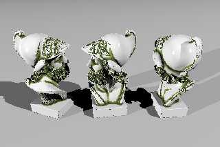
Another test on a more complex mesh object. Here I have run 3 different
instances. Note each one has to be run separately and translated/rotated before
running the algorithm, otherwise the untraced areas would be visible.
Here the general object size is 200units high. Crevice checking is done for a
control depth of 15units, normal angle of 75deg, 16 traces per point.
I also changed the object I am using to show my crevice solouring, I am now
using mesh 'pixels' that extend back into the camera point (mesh because they
are a 4-sided pyramid of sorts), but intersected with the base object. This way
I get a sharp transition from each pixel, with no overlap. One downfall of this
is that I have to texture my base object after using it in the grime (or use an
untextured instance) as the intersection CSG operation causes my grime pixel to
adopt the base object texture otherwise.
The grime is a little pixelated here, because my general pixel size is ~2x that
for the image resolution.
-tgq
Post a reply to this message
Attachments:
Download 'trace3.jpg' (113 KB)
Preview of image 'trace3.jpg'

|
 |
|  |
|  |
|
 |
|
 |
|  |
|  |
|
 |
On 03/15/2011 01:17 PM, Trevor G Quayle wrote:
> Another test on a more complex mesh object. Here I have run 3 different
> instances. Note each one has to be run separately and translated/rotated before
> running the algorithm, otherwise the untraced areas would be visible.
>
> Here the general object size is 200units high. Crevice checking is done for a
> control depth of 15units, normal angle of 75deg, 16 traces per point.
>
> I also changed the object I am using to show my crevice solouring, I am now
> using mesh 'pixels' that extend back into the camera point (mesh because they
> are a 4-sided pyramid of sorts), but intersected with the base object. This way
> I get a sharp transition from each pixel, with no overlap. One downfall of this
> is that I have to texture my base object after using it in the grime (or use an
> untextured instance) as the intersection CSG operation causes my grime pixel to
> adopt the base object texture otherwise.
>
> The grime is a little pixelated here, because my general pixel size is ~2x that
> for the image resolution.
>
> -tgq
hey wow ... making some progress! Did they link I put up spark an idea?
Post a reply to this message
|
 |
|  |
|  |
|
 |
|
 |
|  |


![]()