 |
 |
|
 |
|
 |
|  |
|  |
|
 |
|
 |
|  |
|  |
|
 |
Hi there,
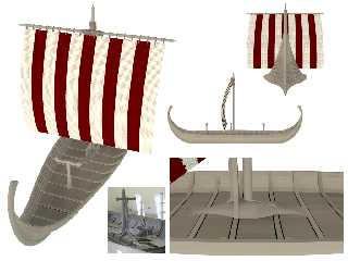
The Viking ship is progressing slowly. The bump in the hull is now fixed,
the deck is complete, and the mastfish is in place (still missing braces on
the ends). There are some major problems, though. For example, the deck is
supposed to stay relatively flat instead of curving upward at the ends. I
thought it was supposed to curve upward, now it's too late to fix without
starting over. Also, the most obvious problem is the shape of the sail. The
bottom corners are supposed to curve backward since there's no crossbeam at
the bottom of the sail. I'm not smart enough to do that. In fact, right now
I feel like the kid in this Far Side cartoon:
http://ircamera.as.arizona.edu/NatSci102/images/extbrainfull.htm
Any suggestions or critcisms are appreciated...
Regards,
Dave
Post a reply to this message
Attachments:
Download 'views.png' (553 KB)
Preview of image 'views.png'

|
 |
|  |
|  |
|
 |
|
 |
|  |
|  |
|
 |
I would be interested to know how the sides were accomplished with the
overlapping boards. Very nice so far!
--
Post a reply to this message
|
 |
|  |
|  |
|
 |
|
 |
|  |
|  |
|
 |
"Halbert" <hal### [at] gmail com> wrote:
> I would be interested to know how the sides were accomplished with the
> overlapping boards. Very nice so far!
>
> --
Hi Halbert,
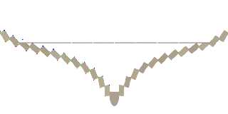
This cross section will help show how the boards (called strakes) overlap.
The colored dots in the picture are markers to help me write to code. The
red dots represent a starting location for each strake. The green dots
represent a target location where that strake should end, after being
rotated a specified amount. The starting location for the next strake can
then be computed based on where the previous one ended. The strakes are
created from the bottom upward. The original start and target locations are
saved in arrays for future use.
The actual ship is made of hundreds of cross section segments individually
sized.
This method of construction has several advantages: First, I wanted to be
able to make the hull narrower at the ends without changing the thickness
of the sides. Simply using the "scale" command on the hull would have also
made the walls of the ship thinner. By changing the start and target
locations of the strakes, the hull can be narrowed without changing the
thickness of the strakes.
Second, POV can do most of the work in creating the profile of the hull. All
I had to do was make a table of angles to rotate each strake. I can
experiment with the angles easily and POV will adjust the positions of all
the strakes for me.
Here's the code to make the hull cross section: (The ".9" factor controls
how far the strakes overlap.)
#macro DefineHullProfile (StrakeThickness, KeelWidth, KeelHeight)
#declare MasterTargetLocation = array [15]
#declare MasterStartLocation = array [15]
#local StrakeWidth = .14;
#declare StrakeAngle = array [15] {
4, // 0
11, // 1
22, // 2
31, // 3
39, // 4
42, // 5
45, // 6
47, // 7
48, // 8
45, // 9
39, // 10
31, // 11
22, // 12
12, // 13
-.4 // 14
} //array
#local CurX = -KeelWidth / 2;
#local CurY = KeelHeight - .04;
#local I = 0;
#while (I < 15)
#local CurX = CurX - StrakeThickness * cos (radians (StrakeAngle
[I]));
#local CurY = CurY - StrakeThickness * sin (radians (StrakeAngle
[I]));
#declare MasterStartLocation [I] = <CurX, CurY, 0>;
#local TargetX = CurX - StrakeWidth * cos (radians (-90 + StrakeAngle
[I]));
#local TargetY = CurY - StrakeWidth * sin (radians (-90 + StrakeAngle
[I]));
#declare MasterTargetLocation [I] = <TargetX, TargetY, 0>;
#local CurX = CurX - StrakeWidth * .9 * cos (radians (-90 +
StrakeAngle [I]));
#local CurY = CurY - StrakeWidth * .9 * sin (radians (-90 +
StrakeAngle [I]));
#local I = I + 1;
#end //#while
#declare MasterYOffset = MasterTargetLocation [14].y;
#end //#macro DefineHullProfile com> wrote:
> I would be interested to know how the sides were accomplished with the
> overlapping boards. Very nice so far!
>
> --
Hi Halbert,
This cross section will help show how the boards (called strakes) overlap.
The colored dots in the picture are markers to help me write to code. The
red dots represent a starting location for each strake. The green dots
represent a target location where that strake should end, after being
rotated a specified amount. The starting location for the next strake can
then be computed based on where the previous one ended. The strakes are
created from the bottom upward. The original start and target locations are
saved in arrays for future use.
The actual ship is made of hundreds of cross section segments individually
sized.
This method of construction has several advantages: First, I wanted to be
able to make the hull narrower at the ends without changing the thickness
of the sides. Simply using the "scale" command on the hull would have also
made the walls of the ship thinner. By changing the start and target
locations of the strakes, the hull can be narrowed without changing the
thickness of the strakes.
Second, POV can do most of the work in creating the profile of the hull. All
I had to do was make a table of angles to rotate each strake. I can
experiment with the angles easily and POV will adjust the positions of all
the strakes for me.
Here's the code to make the hull cross section: (The ".9" factor controls
how far the strakes overlap.)
#macro DefineHullProfile (StrakeThickness, KeelWidth, KeelHeight)
#declare MasterTargetLocation = array [15]
#declare MasterStartLocation = array [15]
#local StrakeWidth = .14;
#declare StrakeAngle = array [15] {
4, // 0
11, // 1
22, // 2
31, // 3
39, // 4
42, // 5
45, // 6
47, // 7
48, // 8
45, // 9
39, // 10
31, // 11
22, // 12
12, // 13
-.4 // 14
} //array
#local CurX = -KeelWidth / 2;
#local CurY = KeelHeight - .04;
#local I = 0;
#while (I < 15)
#local CurX = CurX - StrakeThickness * cos (radians (StrakeAngle
[I]));
#local CurY = CurY - StrakeThickness * sin (radians (StrakeAngle
[I]));
#declare MasterStartLocation [I] = <CurX, CurY, 0>;
#local TargetX = CurX - StrakeWidth * cos (radians (-90 + StrakeAngle
[I]));
#local TargetY = CurY - StrakeWidth * sin (radians (-90 + StrakeAngle
[I]));
#declare MasterTargetLocation [I] = <TargetX, TargetY, 0>;
#local CurX = CurX - StrakeWidth * .9 * cos (radians (-90 +
StrakeAngle [I]));
#local CurY = CurY - StrakeWidth * .9 * sin (radians (-90 +
StrakeAngle [I]));
#local I = I + 1;
#end //#while
#declare MasterYOffset = MasterTargetLocation [14].y;
#end //#macro DefineHullProfile
Post a reply to this message
Attachments:
Download 'hullcrosssection.png' (22 KB)
Preview of image 'hullcrosssection.png'

|
 |
|  |
|  |
|
 |
|
 |
|  |
|  |
|
 |
Dave,
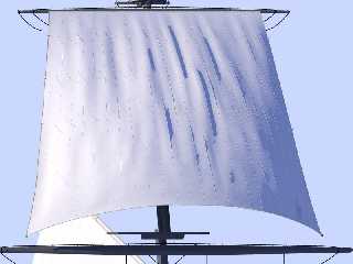
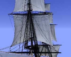
Its good to see another ship builder in here. I like what you have done so
far. I am attaching 2 images of the sails I have modelled for my project.
They were made using the mechanics simulation patch found in Mega-POV. If
you are interested in the technique, I would be more than happy to help you
out.
Tim
Post a reply to this message
Attachments:
Download 'MTop IO Test.JPG' (45 KB)
Download 'USS Niagara 100304.JPG' (153 KB)
Preview of image 'MTop IO Test.JPG'

Preview of image 'USS Niagara 100304.JPG'

|
 |
|  |
|  |
|
 |
|
 |
|  |
|  |
|
 |
"Merrin Cullen" <tim### [at] woh rr rr com> schreef in bericht
news:45ef4ee9@news.povray.org...
> Dave,
>
> Its good to see another ship builder in here. I like what you have done so
> far. I am attaching 2 images of the sails I have modelled for my project.
> They were made using the mechanics simulation patch found in Mega-POV. If
> you are interested in the technique, I would be more than happy to help
> you out.
>
Hey! That looks good! When I find the time to work again on my 17th century
VOC ship, I shall explore those avenues.
Thomas com> schreef in bericht
news:45ef4ee9@news.povray.org...
> Dave,
>
> Its good to see another ship builder in here. I like what you have done so
> far. I am attaching 2 images of the sails I have modelled for my project.
> They were made using the mechanics simulation patch found in Mega-POV. If
> you are interested in the technique, I would be more than happy to help
> you out.
>
Hey! That looks good! When I find the time to work again on my 17th century
VOC ship, I shall explore those avenues.
Thomas
Post a reply to this message
|
 |
|  |
|  |
|
 |
|
 |
|  |
|  |
|
 |
Wow, very impressive! The rigging detail is amazing... For now, I'm going to
keep using the official version of POV. I wish the cloth features had made
their way to the official version. I am curious, though, how difficult was
it to create your sails with Mega-POV?
The sail I'm using now is woven from thousands of "S"-shaped segments and I
can only figure out how to bend it in one dimension at a time. I'll
probably put it aside for a while and work on other things, and maybe I'll
think of a way to make it work.
Regards,
Dave
Post a reply to this message
|
 |
|  |
|  |
|
 |
|
 |
|  |
|  |
|
 |
-----BEGIN PGP SIGNED MESSAGE-----
Hash: SHA1
Dave Blandston wrote:
> Wow, very impressive! The rigging detail is amazing... For now, I'm going to
> keep using the official version of POV. I wish the cloth features had made
> their way to the official version. I am curious, though, how difficult was
> it to create your sails with Mega-POV?
>
> The sail I'm using now is woven from thousands of "S"-shaped segments and I
> can only figure out how to bend it in one dimension at a time. I'll
> probably put it aside for a while and work on other things, and maybe I'll
> think of a way to make it work.
>
Then you can take a look here for a cloth simulator that's
independent but will output povray meshes:
http://jeberger.free.fr/povray/cloth/cloth.html
Jerome
- --
+------------------------- Jerome M. BERGER ---------------------+
| mailto:jeb### [at] free fr | ICQ: 238062172 |
| http://jeberger.free.fr/ | Jabber: jeb### [at] jabber fr | ICQ: 238062172 |
| http://jeberger.free.fr/ | Jabber: jeb### [at] jabber fr |
+---------------------------------+------------------------------+
-----BEGIN PGP SIGNATURE-----
Version: GnuPG v1.4.7 (GNU/Linux)
iD8DBQFF8mAJd0kWM4JG3k8RAhrWAKCxCpF9woYjVKsgK5iXJUSthuFXLgCdGQ+B
j+O3jTStz36ytcF2myj7tyI=
=kbOy
-----END PGP SIGNATURE----- fr |
+---------------------------------+------------------------------+
-----BEGIN PGP SIGNATURE-----
Version: GnuPG v1.4.7 (GNU/Linux)
iD8DBQFF8mAJd0kWM4JG3k8RAhrWAKCxCpF9woYjVKsgK5iXJUSthuFXLgCdGQ+B
j+O3jTStz36ytcF2myj7tyI=
=kbOy
-----END PGP SIGNATURE-----
Post a reply to this message
|
 |
|  |
|  |
|
 |
|
 |
|  |
|  |
|
 |
> Then you can take a look here for a cloth simulator that's
> independent but will output povray meshes:
> http://jeberger.free.fr/povray/cloth/cloth.html
>
> Jerome
That's a great alternative. If I can't get my woven sail to bend around I'll
give that a try. Thanks for the suggestion!
Regards,
Dave
Post a reply to this message
|
 |
|  |
|  |
|
 |
|
 |
|  |


![]()