|
 |
On 12/22/2017 10:21 AM, Bald Eagle wrote:
> William F Pokorny <ano### [at] anonymous org> wrote:
>
>> You've got it. That is exactly what I'm doing, but where that sort of
>> image has been translated into a plane of a df3 density file.
>
> So, just a single layer of voxels in that unit cube - in the x-y plane.
>
For the shape yes. I also buffer on all sides with 5 voxels at 0 to
avoid the density_files edge effects during interpolation.
>
>> #declare FnctTheDF3 = function {
>> pattern{density_file df3 "the.df3" interpolate 3 // 1 if no patch
>> translate -0.5
>> scale 1+(10/800) // lose df3 side buffer padding.
>> translate 0.5
>
> I'm assuming the unit cube extends from <0, 0, 0> to <1, 1, 1>
> so you translate -0.5 to center on the origin, scale, then shift back.
>
Yes, and I should correct the line:
scale 1+(10/800)
which worked for what I was doing, but it was an approximation. A better
scale up - to push the buffer voxels outside the unit square - would be
oriented only in x and y and be adjust for the df3 dimensions.
...
#declare VarPadding = 5;
#declare PadScaleXY =
<Df3Range.x/(Df3Range.x-2*VarPadding),
Df3Range.y/(Df3Range.y-2*VarPadding),1.0>;
...
translate -0.5
scale PadScaleXY
translate 0.5
...
>
>> scale NrmScale*<0,0,3>+<1,1,0> // to thin plane, z 3x thicken
>> translate <0,0,0.5> // Set box width to 1.0.
>
> Then you shift the df3 "back" to get the front layer at z=0
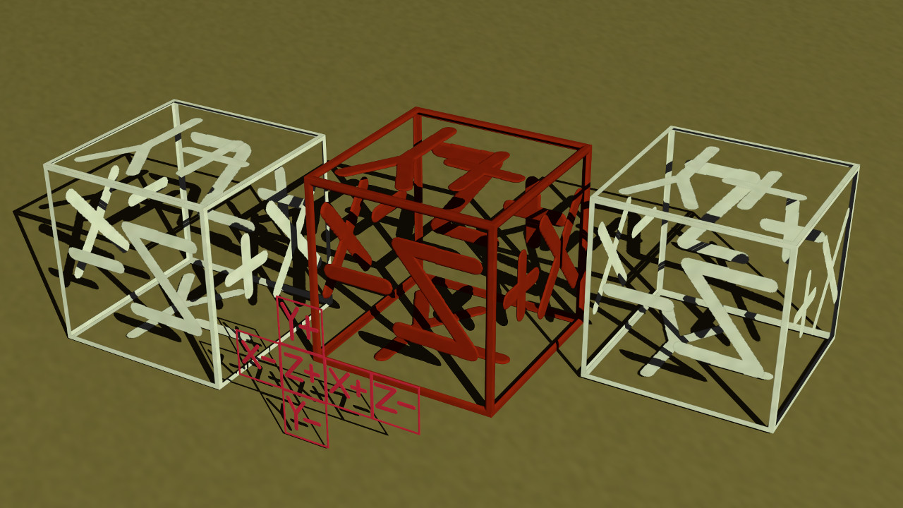
Yes and then the 0.5 offset to set the half width (radius for other map
types) during the warp - this last part has to do with how the warp{}
mapping works. The deep pink isosurface shape in the attached image more
or less shows the shape as it would exist at z=0.5 inside the unit cube
after that last translate.
>
>> warp{cubic} // Wrap pattern around origin.
>> warp{turbulence 0.04 octaves 5 omega 0.4 lambda 5} }
>> }
>
> I suppose it ought to be simple enough to write a macro that assembles such a
> map from a square, or add an internal function that does the same.
>
>
Yes, I think many ways possible to create the df3 plane(1) including
variations of the cubicMap.pov code attached earlier to this thread.
Your news post timing was good because I also need to make a correction
to the code snippet I posted.
The z passed to the pattern based function needs to be flipped to match
the in built in uv_maping for a box object and the warp{cubic} of an
image_map applied to box. These two more routine results being the left
and right white textured boxes in the attached image.
In other words where I had:
#declare Fn00 = function (x,y,z) { 0.025-(FnctTheDF3(x,y,z)) }
it needs to be:
#declare Fn00 = function (x,y,z) { 0.025-(FnctTheDF3(x,y,-z)) }
for the resultant isosurface (center box in the image) to match the two
other cubic maps. Off the top of my head, I'm unsure why the inversion
in z when used in the isosurface... I didn't notice the z-flip until I
tried my first non-symmetric map earlier today.
Bill P.
(1) - It need not be just one plane. We could create boxes within boxes
for example as one media/isosurface at the cost of the df3 getting
deeper/larger to do it. org> wrote:
>
>> You've got it. That is exactly what I'm doing, but where that sort of
>> image has been translated into a plane of a df3 density file.
>
> So, just a single layer of voxels in that unit cube - in the x-y plane.
>
For the shape yes. I also buffer on all sides with 5 voxels at 0 to
avoid the density_files edge effects during interpolation.
>
>> #declare FnctTheDF3 = function {
>> pattern{density_file df3 "the.df3" interpolate 3 // 1 if no patch
>> translate -0.5
>> scale 1+(10/800) // lose df3 side buffer padding.
>> translate 0.5
>
> I'm assuming the unit cube extends from <0, 0, 0> to <1, 1, 1>
> so you translate -0.5 to center on the origin, scale, then shift back.
>
Yes, and I should correct the line:
scale 1+(10/800)
which worked for what I was doing, but it was an approximation. A better
scale up - to push the buffer voxels outside the unit square - would be
oriented only in x and y and be adjust for the df3 dimensions.
...
#declare VarPadding = 5;
#declare PadScaleXY =
<Df3Range.x/(Df3Range.x-2*VarPadding),
Df3Range.y/(Df3Range.y-2*VarPadding),1.0>;
...
translate -0.5
scale PadScaleXY
translate 0.5
...
>
>> scale NrmScale*<0,0,3>+<1,1,0> // to thin plane, z 3x thicken
>> translate <0,0,0.5> // Set box width to 1.0.
>
> Then you shift the df3 "back" to get the front layer at z=0
Yes and then the 0.5 offset to set the half width (radius for other map
types) during the warp - this last part has to do with how the warp{}
mapping works. The deep pink isosurface shape in the attached image more
or less shows the shape as it would exist at z=0.5 inside the unit cube
after that last translate.
>
>> warp{cubic} // Wrap pattern around origin.
>> warp{turbulence 0.04 octaves 5 omega 0.4 lambda 5} }
>> }
>
> I suppose it ought to be simple enough to write a macro that assembles such a
> map from a square, or add an internal function that does the same.
>
>
Yes, I think many ways possible to create the df3 plane(1) including
variations of the cubicMap.pov code attached earlier to this thread.
Your news post timing was good because I also need to make a correction
to the code snippet I posted.
The z passed to the pattern based function needs to be flipped to match
the in built in uv_maping for a box object and the warp{cubic} of an
image_map applied to box. These two more routine results being the left
and right white textured boxes in the attached image.
In other words where I had:
#declare Fn00 = function (x,y,z) { 0.025-(FnctTheDF3(x,y,z)) }
it needs to be:
#declare Fn00 = function (x,y,z) { 0.025-(FnctTheDF3(x,y,-z)) }
for the resultant isosurface (center box in the image) to match the two
other cubic maps. Off the top of my head, I'm unsure why the inversion
in z when used in the isosurface... I didn't notice the z-flip until I
tried my first non-symmetric map earlier today.
Bill P.
(1) - It need not be just one plane. We could create boxes within boxes
for example as one media/isosurface at the cost of the df3 getting
deeper/larger to do it.
Post a reply to this message
Attachments:
Download 'isoboxcubicmap.jpg' (212 KB)
Preview of image 'isoboxcubicmap.jpg'
|
|