|
 |
Josh English <Jos### [at] joshuarenglish com> wrote:
>
> For the anaglyph, remember you can also include the mesh AS AN OBJECT in
> the scene itself. Jaime's Vignette code does this. The mesh_camera
> doesn't sit on the mesh, but starts the rays just offset from the mesh.
> So you may be able to include them and tint them ... oh, yeah. I see the
> problem. You can't group real world objects with individual rays in the
> definition. Maybe build the scene in two sets, and two copies of the
> mesh with the tinted overlays for each set (or, at that point, large
> semi transparent spheres around each set would do it).
>
> Just a thought.
>
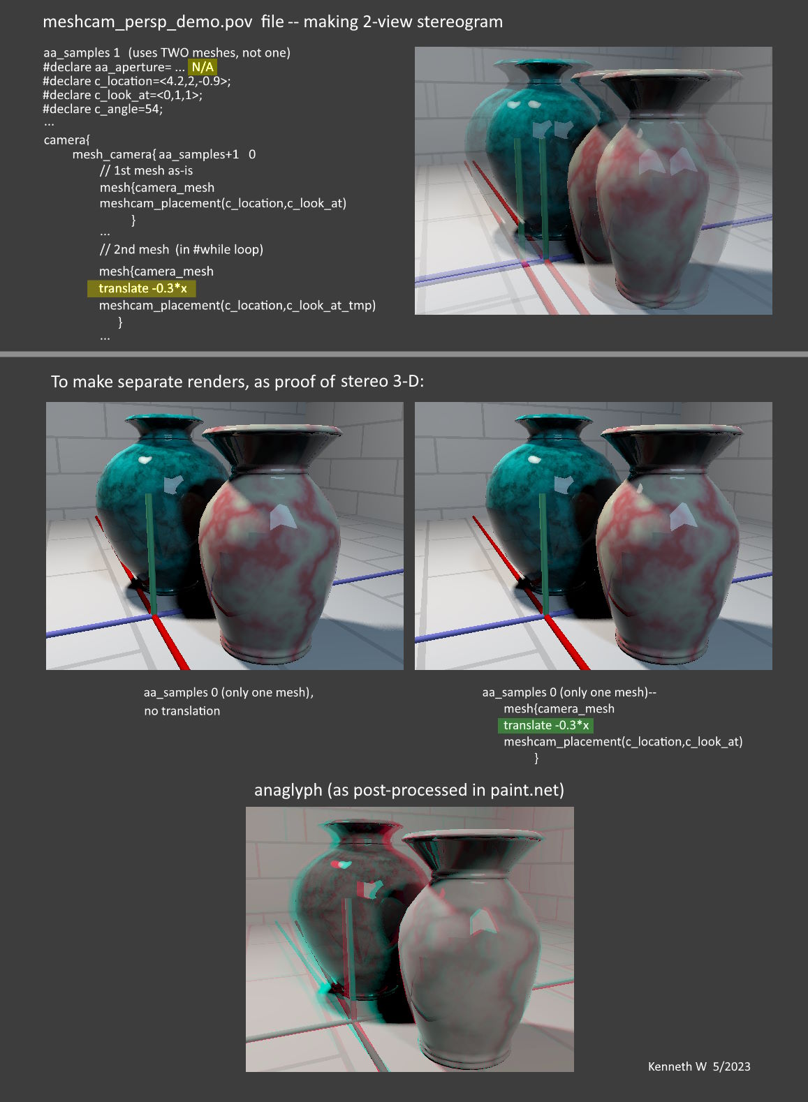
SO... I've been concentrating on the 'meshcam_persp.demo' scene, and came up
with a way to easily generate a two-'camera' stereo view, at least as the
*basics* of a 3D anaglyph. It's the same set-up as the motion-blur code, but
using only two 'eyes'. The camera's initial position doesn't actually change;
it's the camera's mesh that is displaced, which has the same effect. Honestly,
I was not *sure* that this trick produced a true 3-D effect, so I had to prove
it to myself with a different test set-up.
(It would seem that the 'meshcam_stereo_demo' scene would be the logical choice
for my experiments, but I have not yet been able to *overlap* the two images
there instead of being side-by-side. My math attempts have been woefully crude
and unsuccessful.)
In the attached image, the center-row renders are the same as in the overlapped
stereogram. If you can cross your eyes, you'll see the nice 3-D effect. My color
anaglyph example had to be made in a separate app though. I hope the 3-D effect
is apparent, as my red-cyan glasses are actually a very dense and
non-standard(?) red/GREEN. I had to fudge the colors somewhat, as well as image
brightness etc.
So far, my attempts to color each of the two views as red/cyan, *within* the
meshcam scene, have all failed. I've tried using the instantiated meshes as
objects...or semi-transparent spheres... or even tiny thin cylinders and discs--
but they interfere with each other in an odd way when used in pairs, and ruin
the effect. For a *single* camera view (only one mesh), an instantiated/colored
mesh works very well-- but not with two views that overlap. As you alluded to,
the mesh-as-CAMERA and the mesh-as-INSTANTIATED-into-the-scene behave completely
differently. That's difficult to visualize and explain though.
Here are some interesting little facts that I've learned along the way:
1) The camera mesh is curved-- like a section of a sphere surface-- and is not
actually at the given 'c_location'; that's the CENTER of the 'sphere'. And the
spherical diameter depends on the given 'c_angle'.
2) When the camera-mesh is first constructed in 'meshcam_macros.inc', it is
apparently made facing +z, and centered on the origin (that is, the 'center of
the sphere' is at the origin, I think). Then it's later re-positioned and
re-oriented by the meshcam_placement macro-- like this in the
'meshcam_persp_demo' file:
camera{
mesh_camera{ aa_samples+1 0
mesh{camera_mesh
meshcam_placement(c_location,c_look_at)
}
So, prior to meshcam_placement, the mesh can be moved around (translated) in an
understandable x,y,z way, if you choose to :-)
3) In the 'meshcam_persp_demo' file: When 'aa_samples=0', only one camera mesh
is created. When it's set to 1, TWO meshes are actually made-- but they exactly
overlap and behave like one mesh. In the equations at
#declare c_look_at_tmp=...
it appears that the 2nd mesh should be 'jittered' in its position, but isn't.
I've tried to follow the math there, but I don't yet see why the 2nd one is not
being moved. (If aa_samples=2, the 3rd mesh IS jittered.) HOWEVER, when using
aa_samples=1, the 2nd mesh can be easily exploited to create a stereogram, which
is the method I used.
Anyway, I hope the attached image is self-explanatory.
More to come (!) com> wrote:
>
> For the anaglyph, remember you can also include the mesh AS AN OBJECT in
> the scene itself. Jaime's Vignette code does this. The mesh_camera
> doesn't sit on the mesh, but starts the rays just offset from the mesh.
> So you may be able to include them and tint them ... oh, yeah. I see the
> problem. You can't group real world objects with individual rays in the
> definition. Maybe build the scene in two sets, and two copies of the
> mesh with the tinted overlays for each set (or, at that point, large
> semi transparent spheres around each set would do it).
>
> Just a thought.
>
SO... I've been concentrating on the 'meshcam_persp.demo' scene, and came up
with a way to easily generate a two-'camera' stereo view, at least as the
*basics* of a 3D anaglyph. It's the same set-up as the motion-blur code, but
using only two 'eyes'. The camera's initial position doesn't actually change;
it's the camera's mesh that is displaced, which has the same effect. Honestly,
I was not *sure* that this trick produced a true 3-D effect, so I had to prove
it to myself with a different test set-up.
(It would seem that the 'meshcam_stereo_demo' scene would be the logical choice
for my experiments, but I have not yet been able to *overlap* the two images
there instead of being side-by-side. My math attempts have been woefully crude
and unsuccessful.)
In the attached image, the center-row renders are the same as in the overlapped
stereogram. If you can cross your eyes, you'll see the nice 3-D effect. My color
anaglyph example had to be made in a separate app though. I hope the 3-D effect
is apparent, as my red-cyan glasses are actually a very dense and
non-standard(?) red/GREEN. I had to fudge the colors somewhat, as well as image
brightness etc.
So far, my attempts to color each of the two views as red/cyan, *within* the
meshcam scene, have all failed. I've tried using the instantiated meshes as
objects...or semi-transparent spheres... or even tiny thin cylinders and discs--
but they interfere with each other in an odd way when used in pairs, and ruin
the effect. For a *single* camera view (only one mesh), an instantiated/colored
mesh works very well-- but not with two views that overlap. As you alluded to,
the mesh-as-CAMERA and the mesh-as-INSTANTIATED-into-the-scene behave completely
differently. That's difficult to visualize and explain though.
Here are some interesting little facts that I've learned along the way:
1) The camera mesh is curved-- like a section of a sphere surface-- and is not
actually at the given 'c_location'; that's the CENTER of the 'sphere'. And the
spherical diameter depends on the given 'c_angle'.
2) When the camera-mesh is first constructed in 'meshcam_macros.inc', it is
apparently made facing +z, and centered on the origin (that is, the 'center of
the sphere' is at the origin, I think). Then it's later re-positioned and
re-oriented by the meshcam_placement macro-- like this in the
'meshcam_persp_demo' file:
camera{
mesh_camera{ aa_samples+1 0
mesh{camera_mesh
meshcam_placement(c_location,c_look_at)
}
So, prior to meshcam_placement, the mesh can be moved around (translated) in an
understandable x,y,z way, if you choose to :-)
3) In the 'meshcam_persp_demo' file: When 'aa_samples=0', only one camera mesh
is created. When it's set to 1, TWO meshes are actually made-- but they exactly
overlap and behave like one mesh. In the equations at
#declare c_look_at_tmp=...
it appears that the 2nd mesh should be 'jittered' in its position, but isn't.
I've tried to follow the math there, but I don't yet see why the 2nd one is not
being moved. (If aa_samples=2, the 3rd mesh IS jittered.) HOWEVER, when using
aa_samples=1, the 2nd mesh can be easily exploited to create a stereogram, which
is the method I used.
Anyway, I hope the attached image is self-explanatory.
More to come (!)
Post a reply to this message
Attachments:
Download 'meshcam_stereo_demo_diagram_kw_5_2023.jpg' (187 KB)
Preview of image 'meshcam_stereo_demo_diagram_kw_5_2023.jpg'
|
|