|
 |
kurtz le pirate <kur### [at] gmail com> wrote:
> On 22/11/2021 17:23, kurtz le pirate wrote:
> > Hello,
> >
> > I have a surface defined by a set of points <x,y,z> and for each point,
> > its color.
> >
> > In your opinion, which object/method is the most appropriate to
> > represent such a surface?
>
>
> I'm moving slowly. I can now build my surface by generating a mesh from
> my set of points exactly as for a height_field.
> But I'm still struggling with the color story.
>
> I have this scheme on the <x,z> plane
>
> +--> z
> |
> V
> x
>
> | | |
> --- * --- * --- * ---
> | | |
> --- * --- * --- * ---
> | | |
> --- * --- * --- * ---
> | | |
> --- * --- * --- * ---
> | | |
>
>
> Each "*" is my points. This points are on a "square grid".
> I convert this grid to triangle. I get :
>
> | | |
> --- * --- * --- * ---
> | / | / |
> | / | / | /
> | / | / | /
> --- * --- * --- * ---
> / | / | / |
> / | / | / | /
> / | / | / | /
> --- * --- * --- * ---
> / | / | / |
> / | / | / | /
> / | / | / | /
> --- * --- * --- * ---
> | | |
>
> I obtain a set of triangles schematized below.
> These triangles compose the mesh which is easy to display.
>
> But ... for the color, I still don't know how to do it :(
> The color is "at" a point "*". impossible to find out how to give the
> color to which triangle.
>
>
> One more time, any suggestion ?
>
>
>
>
>
> --
> Kurtz le pirate
> Compagnie de la Banquise
Hi Kurtz,
I've written the script below to show you how to create a mesh2 object from a
parametric expression of your surface and texture (I don't know how you have
defined your surface, I hope you'll figure out how to adapt the macro with
something else than parametric surfaces if needed).
Pascal
-----------------------------------------------------------------------
#version 3.8;
// Given that you have a parametric expression of the surface a follow:
// Inputs:
// a, b: two floats, the two parameters of the parametric surface.
// The range of values for a and b depends on the surface equation
// but I think it's a good idea to impose it to be [0.0, 1.0] and
// scale it as necessary here, as it avoid having to adapt the
// CreateMesh macro below each time you change the FunShape macro
// Output:
// Return a 3D vector, the coordinates of the surface for the given
// parameters.
#macro FunShape(a, b)
<a, cos(a * pi) * sin(b * pi), b>
#end
// In the exact same fashion as for the parametric shape, lets suppose you have
// a parametric expression of the texture components (here I consider only the
// rgb color, but it could be extended as needed to other texture components)
// Inputs:
// a, b: two floats, the two parameters of the parametric surface (the same
// as FunShape)
// Output:
// Return a 3D vector, the rgb color of the surface for the given parameters
#macro FunColor(a, b)
<a, 0.0, b>
#end
// You may also have an explicit expression of the normals of the surface, but
// if you don't you can get an approximation for free from the surface equation
// as follow:
// Inputs:
// a, b: two floats, the two parameters of the parametric surface
// Output:
// Return a 3D vector, the normal vector of the surface for the given
// parameters.
#macro FunShapeNormal(a, b)
// shapeEpsilon must be set to a small value in comparison to the range
// of values for the parameters a and b. Here too, imposing a and b in
// [0.0, 1.0] avoid having to update shapeEpsilon each time FunShape changes
#local shapeEpsilon = 0.01;
vcross(
FunShape(a + shapeEpsilon, b) - FunShape(a, b),
FunShape(a, b + shapeEpsilon) - FunShape(a, b))
#end
// The macro creating the textured mesh2 object from the parametric expression
// of your surface and texture
#macro CreateMesh()
// Define the resolution of your grid, the higher the nicer the heavier
#local nbStepU = 100;
// You'd probably like to set the same resolution along the two parameters
// but nothing forbid choose different ones
#local nbStepV = nbStepU;
// Starts the mesh2 object
mesh2 {
// Calculate the number of vertices
#local nbVertex = (nbStepU + 1) * (nbStepV + 1);
// Start the vertices definition
vertex_vectors {
nbVertex,
// Loop on the steps along the parameters
#local a = 0;
#while (a <= nbStepU)
#local b = 0;
#while (b <= nbStepV)
// Get the parameters in [0.0, 1.0] from the current steps and
// calculate and add the coordinates of the vertex
FunShape(a / nbStepU , b / nbStepV)
#local b = b + 1;
#end
#local a = a + 1;
#end
// End the vertices definition
}
// Start the normals definition
normal_vectors {
// There is one normal per vertex, hence the reuse of nbVertex
nbVertex,
// Loop on the steps along the parameters
#local a = 0;
#while (a <= nbStepU)
#local b = 0;
#while (b <= nbStepV)
// Get the parameters in [0.0, 1.0] from the current steps and
// calculate and add the normal
FunShapeNormal(a / nbStepU , b / nbStepV)
#local b = b + 1;
#end
#local a = a + 1;
#end
// End the normal definition
}
// Start the textures definition
texture_list {
// There is one texture per vertex, hence the reuse of nbVertex
nbVertex,
// Loop on the steps along the parameters
#local a = 0;
#while (a <= nbStepU)
#local b = 0;
#while (b <= nbStepV)
// Get the parameters in [0.0, 1.0] from the current steps and
// calculate and add the texture. Here it could be extend with
// other parametric functions for the finish{} parameters for
// example
texture { pigment { rgb FunColor(a / nbStepU , b / nbStepV) }}
#local b = b + 1;
#end
#local a = a + 1;
#end
// End the textures definition
}
// Start the faces definition
face_indices {
// Get the number of faces, one step along the two parameters defines a
// polyline of 4 vertices which can be split in two triangles
#local nbFace = nbStepU * nbStepV * 2;
nbFace ,
// There are two ways to split the polyline in two triangles, alternating
// regularly between them gives much better visual results. Set a flag
// to manage that.
#local flipEdge = 0;
// Loop on the steps along the parameters
#local a = 0;
#while (a < nbStepU)
#local b = 0;
#while (b < nbStepV)
// Calculate the indices of the four vertices of the polyline
// corresponding to the current steps
#local indexVertices = array {
a * (nbStepV + 1) + b,
a * (nbStepV + 1) + b + 1,
(a + 1) * (nbStepV + 1) + b,
(a + 1) * (nbStepV + 1) + b + 1,
};
// Switch between the two ways of splitting the polyline
#if (flipEdge = 0)
// Add the first face definition
<indexVertices[0],indexVertices[1],indexVertices[3]>,
// Add the texture indices, as we have conveniently defined the
// texture in the same order as the vertices, their indices are
// identical
indexVertices[0],indexVertices[1],indexVertices[3]
// Same for the second face definition
<indexVertices[0],indexVertices[3],indexVertices[2]>,
indexVertices[0],indexVertices[3],indexVertices[2]
#else
// Same as flipEdge=1 but with the other combination of indices
<indexVertices[0],indexVertices[1],indexVertices[2]>,
indexVertices[0],indexVertices[1],indexVertices[2]
<indexVertices[1],indexVertices[3],indexVertices[2]>,
indexVertices[1],indexVertices[3],indexVertices[2]
#end
// Flip the splitting
#local flipEdge = 1 - flipEdge;
#local b = b + 1;
#end
#local a = a + 1;
#end
// End the faces definition
}
// End the mesh2 object
}
#end
// Instantiate the mesh
object {
CreateMesh()
translate -0.5*x-0.5*z
}
// Dummy settings for test rendering
global_settings {assumed_gamma 1.0}
background { color rgb 0 }
camera { location 1.5 look_at 0 }
light_source { 1.5 color rgb 1 }
----------------------------------------------------------------------- com> wrote:
> On 22/11/2021 17:23, kurtz le pirate wrote:
> > Hello,
> >
> > I have a surface defined by a set of points <x,y,z> and for each point,
> > its color.
> >
> > In your opinion, which object/method is the most appropriate to
> > represent such a surface?
>
>
> I'm moving slowly. I can now build my surface by generating a mesh from
> my set of points exactly as for a height_field.
> But I'm still struggling with the color story.
>
> I have this scheme on the <x,z> plane
>
> +--> z
> |
> V
> x
>
> | | |
> --- * --- * --- * ---
> | | |
> --- * --- * --- * ---
> | | |
> --- * --- * --- * ---
> | | |
> --- * --- * --- * ---
> | | |
>
>
> Each "*" is my points. This points are on a "square grid".
> I convert this grid to triangle. I get :
>
> | | |
> --- * --- * --- * ---
> | / | / |
> | / | / | /
> | / | / | /
> --- * --- * --- * ---
> / | / | / |
> / | / | / | /
> / | / | / | /
> --- * --- * --- * ---
> / | / | / |
> / | / | / | /
> / | / | / | /
> --- * --- * --- * ---
> | | |
>
> I obtain a set of triangles schematized below.
> These triangles compose the mesh which is easy to display.
>
> But ... for the color, I still don't know how to do it :(
> The color is "at" a point "*". impossible to find out how to give the
> color to which triangle.
>
>
> One more time, any suggestion ?
>
>
>
>
>
> --
> Kurtz le pirate
> Compagnie de la Banquise
Hi Kurtz,
I've written the script below to show you how to create a mesh2 object from a
parametric expression of your surface and texture (I don't know how you have
defined your surface, I hope you'll figure out how to adapt the macro with
something else than parametric surfaces if needed).
Pascal
-----------------------------------------------------------------------
#version 3.8;
// Given that you have a parametric expression of the surface a follow:
// Inputs:
// a, b: two floats, the two parameters of the parametric surface.
// The range of values for a and b depends on the surface equation
// but I think it's a good idea to impose it to be [0.0, 1.0] and
// scale it as necessary here, as it avoid having to adapt the
// CreateMesh macro below each time you change the FunShape macro
// Output:
// Return a 3D vector, the coordinates of the surface for the given
// parameters.
#macro FunShape(a, b)
<a, cos(a * pi) * sin(b * pi), b>
#end
// In the exact same fashion as for the parametric shape, lets suppose you have
// a parametric expression of the texture components (here I consider only the
// rgb color, but it could be extended as needed to other texture components)
// Inputs:
// a, b: two floats, the two parameters of the parametric surface (the same
// as FunShape)
// Output:
// Return a 3D vector, the rgb color of the surface for the given parameters
#macro FunColor(a, b)
<a, 0.0, b>
#end
// You may also have an explicit expression of the normals of the surface, but
// if you don't you can get an approximation for free from the surface equation
// as follow:
// Inputs:
// a, b: two floats, the two parameters of the parametric surface
// Output:
// Return a 3D vector, the normal vector of the surface for the given
// parameters.
#macro FunShapeNormal(a, b)
// shapeEpsilon must be set to a small value in comparison to the range
// of values for the parameters a and b. Here too, imposing a and b in
// [0.0, 1.0] avoid having to update shapeEpsilon each time FunShape changes
#local shapeEpsilon = 0.01;
vcross(
FunShape(a + shapeEpsilon, b) - FunShape(a, b),
FunShape(a, b + shapeEpsilon) - FunShape(a, b))
#end
// The macro creating the textured mesh2 object from the parametric expression
// of your surface and texture
#macro CreateMesh()
// Define the resolution of your grid, the higher the nicer the heavier
#local nbStepU = 100;
// You'd probably like to set the same resolution along the two parameters
// but nothing forbid choose different ones
#local nbStepV = nbStepU;
// Starts the mesh2 object
mesh2 {
// Calculate the number of vertices
#local nbVertex = (nbStepU + 1) * (nbStepV + 1);
// Start the vertices definition
vertex_vectors {
nbVertex,
// Loop on the steps along the parameters
#local a = 0;
#while (a <= nbStepU)
#local b = 0;
#while (b <= nbStepV)
// Get the parameters in [0.0, 1.0] from the current steps and
// calculate and add the coordinates of the vertex
FunShape(a / nbStepU , b / nbStepV)
#local b = b + 1;
#end
#local a = a + 1;
#end
// End the vertices definition
}
// Start the normals definition
normal_vectors {
// There is one normal per vertex, hence the reuse of nbVertex
nbVertex,
// Loop on the steps along the parameters
#local a = 0;
#while (a <= nbStepU)
#local b = 0;
#while (b <= nbStepV)
// Get the parameters in [0.0, 1.0] from the current steps and
// calculate and add the normal
FunShapeNormal(a / nbStepU , b / nbStepV)
#local b = b + 1;
#end
#local a = a + 1;
#end
// End the normal definition
}
// Start the textures definition
texture_list {
// There is one texture per vertex, hence the reuse of nbVertex
nbVertex,
// Loop on the steps along the parameters
#local a = 0;
#while (a <= nbStepU)
#local b = 0;
#while (b <= nbStepV)
// Get the parameters in [0.0, 1.0] from the current steps and
// calculate and add the texture. Here it could be extend with
// other parametric functions for the finish{} parameters for
// example
texture { pigment { rgb FunColor(a / nbStepU , b / nbStepV) }}
#local b = b + 1;
#end
#local a = a + 1;
#end
// End the textures definition
}
// Start the faces definition
face_indices {
// Get the number of faces, one step along the two parameters defines a
// polyline of 4 vertices which can be split in two triangles
#local nbFace = nbStepU * nbStepV * 2;
nbFace ,
// There are two ways to split the polyline in two triangles, alternating
// regularly between them gives much better visual results. Set a flag
// to manage that.
#local flipEdge = 0;
// Loop on the steps along the parameters
#local a = 0;
#while (a < nbStepU)
#local b = 0;
#while (b < nbStepV)
// Calculate the indices of the four vertices of the polyline
// corresponding to the current steps
#local indexVertices = array {
a * (nbStepV + 1) + b,
a * (nbStepV + 1) + b + 1,
(a + 1) * (nbStepV + 1) + b,
(a + 1) * (nbStepV + 1) + b + 1,
};
// Switch between the two ways of splitting the polyline
#if (flipEdge = 0)
// Add the first face definition
<indexVertices[0],indexVertices[1],indexVertices[3]>,
// Add the texture indices, as we have conveniently defined the
// texture in the same order as the vertices, their indices are
// identical
indexVertices[0],indexVertices[1],indexVertices[3]
// Same for the second face definition
<indexVertices[0],indexVertices[3],indexVertices[2]>,
indexVertices[0],indexVertices[3],indexVertices[2]
#else
// Same as flipEdge=1 but with the other combination of indices
<indexVertices[0],indexVertices[1],indexVertices[2]>,
indexVertices[0],indexVertices[1],indexVertices[2]
<indexVertices[1],indexVertices[3],indexVertices[2]>,
indexVertices[1],indexVertices[3],indexVertices[2]
#end
// Flip the splitting
#local flipEdge = 1 - flipEdge;
#local b = b + 1;
#end
#local a = a + 1;
#end
// End the faces definition
}
// End the mesh2 object
}
#end
// Instantiate the mesh
object {
CreateMesh()
translate -0.5*x-0.5*z
}
// Dummy settings for test rendering
global_settings {assumed_gamma 1.0}
background { color rgb 0 }
camera { location 1.5 look_at 0 }
light_source { 1.5 color rgb 1 }
-----------------------------------------------------------------------
Post a reply to this message
Attachments:
Download 'surface2mesh.jpg' (21 KB)
Preview of image 'surface2mesh.jpg'
|
|
|
|
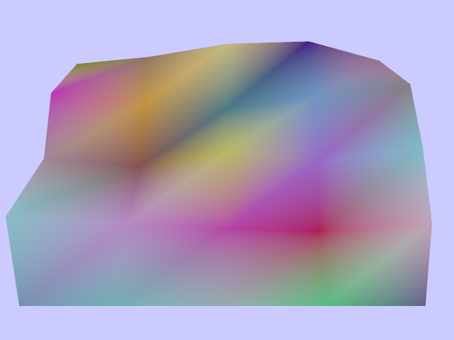
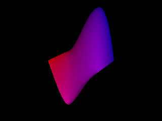
kurtz le pirate <kur### [at] gmailcom> wrote:
>
>...
> My problem is not the geometry but its coloring.
>
> My script generates a mesh (that I can save to use later). I get for
> example this surface. it is a "3d" representation of the function
> f(z) = (-z^3 + iz^2 + 1) / (z - 1 + i)^2
>
> Without going into details and according with "Domain coloring", the
> color of each point of f(z) is defined by its argument which is an angle
> ... and which corresponds to the hue.
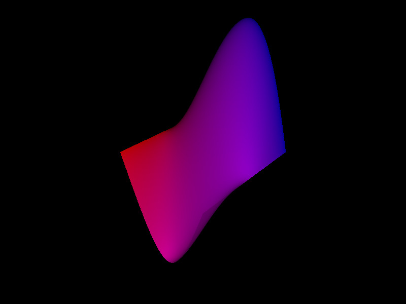
Hi Kurtz
Assuming your z is a complex variable with a real and imaginary part,
and that you plot the magnitude of your function as the height (along
POV-Ray's y-axis) over a complex plane with the real part along POV-
Ray's x-axis and the imaginary part along POV-Ray's z-axis then you
can use the argument (0 to 2*pi) of your function to choose a color
from a color map, like this:
// ===== 1 ======= 2 ======= 3 ======= 4 ======= 5 ======= 6 ======= 7
#version 3.7;
#declare Tau = 2*pi;
#declare YourMesh = mesh2 { ... }
#declare YourArgFn = function { ... };
#declare ColorWheel =
color_map {
[ 0/6 color rgb <1, 0, 0> ]
[ 1/6 color rgb <1, 1, 0> ]
[ 2/6 color rgb <0, 1, 0> ]
[ 3/6 color rgb <0, 1, 1> ]
[ 4/6 color rgb <0, 0, 1> ]
[ 5/6 color rgb <1, 0, 1> ]
[ 6/6 color rgb <1, 0, 0> ]
}
object {
YourMesh
pigment {
function { YourArgFn(x, 0, z)/Tau }
color_map { ColorWheel }
}
}
// ===== 1 ======= 2 ======= 3 ======= 4 ======= 5 ======= 6 ======= 7
--
Tor Olav
http://subcube.com
https://github.com/t-o-k
Post a reply to this message
|
|