|
|
|
|
|
|
| |
| |
|
|
|
|
| |
| |
|
|
>> Now try doing that with a sound that's been LZW-compressed. ;-)
>>
>> Doesn't sound very nice...
>
> I imagine it's about as pleasing as loading an MP3 as a raw PCM audio
> file and playing it.
Yes.
Indeed, *any* data compressed with an efficient compression algorithm
should sound roughly like white noise. If it doesn't, further
compression should be possible.
> For some reason this one audio app I have
> recognizes every MP3 correctly, except for a handful of files from one
> particular album. Weird.
Maybe the audio app is looking for the ID3 tag or something, and these
few files don't have one? Who knows...
Post a reply to this message
|
|
| |
| |
|
|
|
|
| |
| |
|
|
Invisible wrote:
> Maybe the audio app is looking for the ID3 tag or something, and these
> few files don't have one? Who knows...
I think they may have an ID3v2 tag in a non-standard location.
--
~Mike
Post a reply to this message
|
|
| |
| |
|
|
|
|
| |
| |
|
|
Invisible wrote:
> A Chebyshev low-pass filter arranges poles in a semicircle. The
> resonance comes from deforming this circle to make it elliptical. As you
> do so, the poles get nearer to the line, and the "ripples" you see are
> actually the edges of the peak surrounding each pole. I'll draw you a
> graph if you like... ;-)
...and what *is* the most advanced graphing tool known?
Yeah, that's right! ;-)
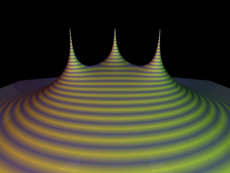
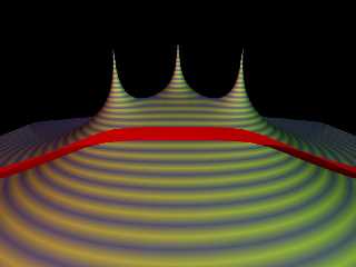
The first image shows a plot of the transfer function for a 3-pole
Butterworth filter. (I.e., a lowpass filter with 0% ripple.) You can't
see it terribly well from this angle, but those three mountain peaks
(poles) are arraned in a semicircle.
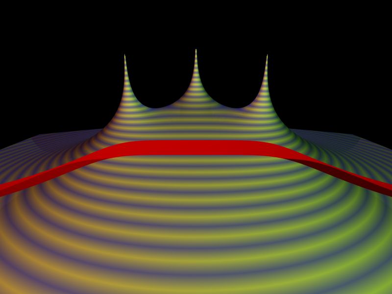
The second image is the same thing, but I've cut a slice through the
graph along the critical line to reveal the filter's frequency response
(red). As you can see, it's flat in the middle, and tapers down at
either side. (The X-axis is frequency, with 0 Hz in the middle and
negative/positive frequencies on each side.) Normally you'd look at the
s-domain the other way round, but in 3D you can't see the cut very well,
so I've rotated it.
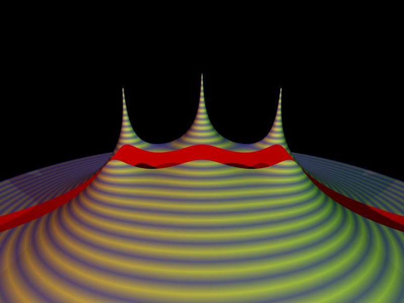
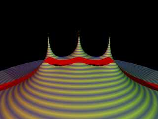
The third image is the same as the second, except that I've made the
semicircle elliptical. (You can't see this very much with this camera
angle. Feel free to change it...) Notice how the frequency response now
has "ripples" - corresponding to the edges of the peaks.
The radius of the circle is the cutoff frequency, and the
ellipticallness is the ripple (and cutoff slope). The parts to fiddle
with are the lines that #define the R1-R3 and I1-I3 variables. Set the
radius of both equal for a Butterworth filter, and then decrease R# only
for Chebyshev.
--
http://blog.orphi.me.uk/
http://www.zazzle.com/MathematicalOrchid*
Post a reply to this message
Attachments:
Download 'iir-02.jpg' (30 KB)
Download 'iir-03.jpg' (31 KB)
Download 'iir-04.jpg' (31 KB)
Download 'us-ascii' (2 KB)
Preview of image 'iir-02.jpg'
Preview of image 'iir-03.jpg'
Preview of image 'iir-04.jpg'
|
|
| |
| |
|
|
|
|
| |
| |
|
|
Orchid XP v8 wrote:
> Invisible wrote:
>
>> A Chebyshev low-pass filter arranges poles in a semicircle. The
>> resonance comes from deforming this circle to make it elliptical. As
>> you do so, the poles get nearer to the line, and the "ripples" you see
>> are actually the edges of the peak surrounding each pole. I'll draw
>> you a graph if you like... ;-)
>
> ...and what *is* the most advanced graphing tool known?
>
> Yeah, that's right! ;-)
>
> The first image shows a plot of the transfer function for a 3-pole
> Butterworth filter. (I.e., a lowpass filter with 0% ripple.) You can't
> see it terribly well from this angle, but those three mountain peaks
> (poles) are arraned in a semicircle.
>
> The second image is the same thing, but I've cut a slice through the
> graph along the critical line to reveal the filter's frequency response
> (red). As you can see, it's flat in the middle, and tapers down at
> either side. (The X-axis is frequency, with 0 Hz in the middle and
> negative/positive frequencies on each side.) Normally you'd look at the
> s-domain the other way round, but in 3D you can't see the cut very well,
> so I've rotated it.
>
> The third image is the same as the second, except that I've made the
> semicircle elliptical. (You can't see this very much with this camera
> angle. Feel free to change it...) Notice how the frequency response now
> has "ripples" - corresponding to the edges of the peaks.
>
> The radius of the circle is the cutoff frequency, and the
> ellipticallness is the ripple (and cutoff slope). The parts to fiddle
> with are the lines that #define the R1-R3 and I1-I3 variables. Set the
> radius of both equal for a Butterworth filter, and then decrease R# only
> for Chebyshev.
>
Gotta love POV-Ray for visualizing a surface. I'm guessing then what the
Q parameter (to the resonant filter) then was adjust the elipticalness
of the surface, then ...
--
~Mike
Post a reply to this message
|
|
| |
| |
|
|
|
|
| |
| |
|
|
>> ...and what *is* the most advanced graphing tool known?
>
> Gotta love POV-Ray for visualizing a surface.
Yeah, you do...
> I'm guessing then what the
> Q parameter (to the resonant filter) then was adjust the elipticalness
> of the surface, then ...
Precisely.
I've you look at the code I posted, I've got
#declare R1 = 0.5*cos(A1); #declare I1 = 2*cos(A1);
...
If you had both of them with "2*", you'd have a no-ripple filter with a
2 Hz cutoff frequency. By making the first coefficient smaller than the
second, you're making the circle more elliptical. I'm not sure precisely
why that makes the rolloff steeper, but it's quite visually "obvious"
why it makes the thing ripple. (At least, I hope it is...)
There's a formula that tells you "how elliptical" you need to make it
for X amount of ripple and Y amount of rolloff. I don't know that
formula off the top of my head...
Post a reply to this message
|
|
| |
| |
|
|
|
|
| |
|
|