|
|
|
|
|
|
| |
| |
|
|
|
|
| |
| |
|
|
On 2026-03-20 19:21 (-4), Bald Eagle wrote:
>
> Post something. It doesn't matter what it is.
> Really. Just post it. Here.
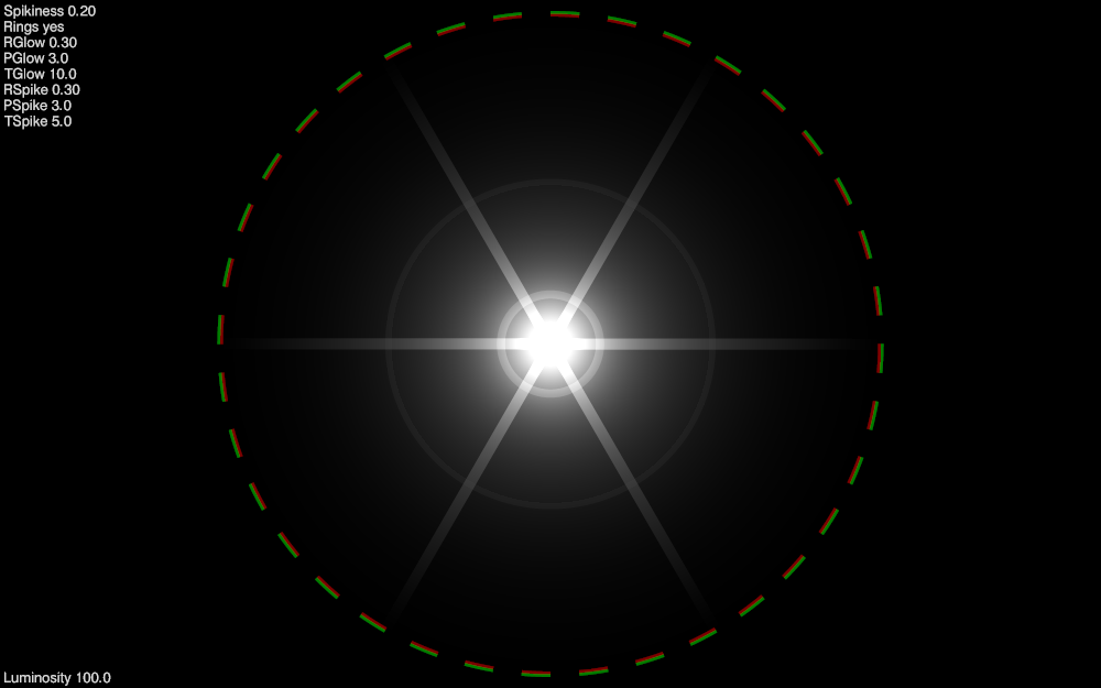
Funny you should mention. I was just at a stopping point with this
experiment for improving my light bleeding code.
Post a reply to this message
Attachments:
Download 'relative_glow.pbi.png' (76 KB)
Preview of image 'relative_glow.pbi.png'
|
|
| |
| |
|
|
|
|
| |
| |
|
|
"Attractors"
When surfing the Web looking for new and interesting pigment patterns that I
could implement, I came across some very cool looking stuff.
The idea is that a pattern is somehow modulated by its proximity to points or
even lines. Any attribute can be modified - size, shape, color, position, some
other more complicated thing like a parameter of the underlying pattern, etc.
I've experimented a little with this in the past, but didn't know that it was a
fully-developed "thing".
Here's a sinc function that modulates the size of 3 different object grids.
https://en.wikipedia.org/wiki/Sinc_function
Post a reply to this message
Attachments:
Download 'demo_attractorgrids.png' (346 KB)
Preview of image 'demo_attractorgrids.png'
|
|
| |
| |
|
|
|
|
| |
| |
|
|
One of the reasons that I started this thread was to try and spur people into
action, and get people who are scattered over the vast interweb to contribute
here in the official POV-Ray newsgroup. Not Facebook, Meta, X, Telegram,
Instagram, YouTube, Discord, etc.
I have too many of my own projects to keep up with - I don't have the time and
attention to multiply posting and answer-searching over a dozen other venues.
Also, since I don't have the time to pursue every new thing that I come across
or need to do as part of a 5-step development, I figured I'd start posting bits
and pieces, so that others might be inspired to pick something up, investigate
it further, and maybe carry it across the finish line.
Some things I "complete" just to demonstrate proof-of-concept.
"No, it's not 'impossible'."
Other things I create from spur-of-the moment necessity, and just continue using
as a matter of practicality.
All of those things could surely be "better", more efficient, and more elegant.
They could also be refactored into durable "production code" with future-proof
structuring of the code and data structures, comments, references, and notes on
future, unfinished improvements.
Perhaps if there is interest - the fruits of this thread could be periodically
packaged into a semantic-versioned archive (zip, 7z, tar.gz) that would help
people expand on the official distribution.
- BE
Post a reply to this message
|
|
| |
| |
|
|
|
|
| |
| |
|
|
One of the things that I have sustained an active interest in over the past
several years is the creation of procedural patterns.
Doing this in SDL to create pigment {function {}} patterns can be challenging
due to the scalar-only nature of the function parser / virtual machine.
During experimentation with infinitely tiling a plane or filling space, it
became readily apparent that the stock modulo function - mod (N, M) - did not
remain consistent across the -value|0|+value transition.
So I crafted my own. And then another. And then another.
So which one was "right"? Apparently this is one of those situation-dependent
functions like pow (0, 0).
So I did some investigating and there are a number of different ways to perform
modular arithmetic so that the result has the specific characteristics that you
need in your given situation. And here's an important note: you may need to use
different behaviours in different parts of your equations.
I discovered that my custom-rolled fmod () function usually worked for what I
needed, but when applied in a blanket manner was inappropriate for certain parts
of my patterns. So I use fmod () some places, and stock mod () in others.
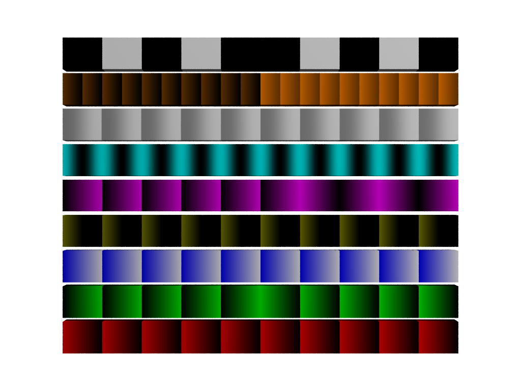
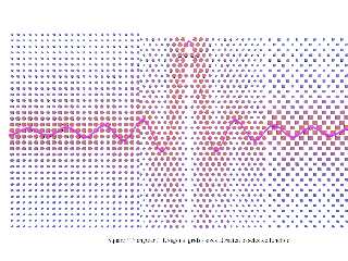
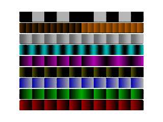
Here's a small starting library. I'm sure there are more variations.
// MODULO_LIB.inc
// Behavioral Modulo Library for POV-Ray SDL
// Guarded, scalar-only, function-safe
#ifndef (MODULO_LIB_INC)
#declare MODULO_LIB_INC = yes;
// --- HARD MODULO ---
#declare MOD_HARD_BASIC = function (V, P) { mod(V, P) };
// --- ABSOLUTE MODULO ---
#declare MOD_ABS_BASIC = function (V, P) { mod(abs(V), P) };
// --- PHASE-CORRECTED ABS MODULO ---
#declare MOD_ABS_PHASE = function (V, P)
{ select(V, 1 - mod(abs(V), P), mod(abs(V), P)) };
// --- CENTERED MODULO ---
#declare MOD_CENTER_BASIC = function (V, P)
{ mod(V + P/2, P) - P/2 };
// --- TRIANGLE MODULO ---
#declare MOD_TRI_BASIC = function (V, P)
{ abs(mod(V, 2*P) - P) };
// --- SMOOTH MODULO ---
#declare MOD_SMOOTH_BASIC = function (V, P)
{ P * (0.5 - 0.5*cos(2*pi*V/P)) };
#declare MOD_SMOOTH_SIGNED = function (V, P)
{ V - P * sin(2*pi*V/P)/(2*pi) };
// --- NESTED MODULO ---
#declare MOD_NEST_BASIC = function (V, A, B)
{ mod(mod(V, A), B) };
#declare MOD_NEST_ABS = function (V, A, B)
{ mod(mod(abs(V), A), B) };
#declare MOD_NEST_PHASE = function (V, A, B)
{ select(V, B - mod(mod(abs(V), A), B), mod(mod(abs(V), A), B)) };
// --- LOGIC MODULO ---
#declare MOD_LOGIC_PARITY = function (V, P)
{ mod(floor(abs(V)/P), 2) };
#declare MOD_LOGIC_QUANTIZED = function (V, P, S)
//{ round(mod(V, P)/S)*S };
{ int(mod(V, P)/S)*S };
// --- WINDOWED / CLAMPED ---
#declare MOD_LOGIC_WINDOW = function (V, P)
{ select(V, mod(abs(V), P), 0) };
#declare MOD_LOGIC_CLAMP = function (V, P, C)
{ min(mod(V, P), C) };
// --- METRIC HELPERS ---
#declare MOD_METRIC_RADIAL = function (R, P)
{ mod(R, P) };
#declare MOD_METRIC_ANGLE = function (A, P)
{ mod(A, P) };
#end
// *** end of file ***
Post a reply to this message
Attachments:
Download 'modulo_lib_full_demo.png' (53 KB)
Preview of image 'modulo_lib_full_demo.png'
|
|
| |
| |
|
|
|
|
| |
| |
|
|
"Bald Eagle" <cre### [at] netscape net> wrote:
> "I tried to get Z to work, but never finished it."
Way back when - when I had lots more time to spend several (mostly)
uninterrupted hours working things out, I coded up an animation of the entire
solar system, which mostly astronomically correct. Plus the asteroid belt.
Everything started out at clock=0, and all the objects were in syzygy.
For all those other folks playing around with such things like orreries, the
important part is adjusting everything for it's specific Mean Anomaly.
January 1, 2000, at 12:00 Terrestrial Time (TT) or Julian Date 2451545.0
Mean anomaly formulation:
M(t) = M0 + 360 * (t - t0)/P
Where:
- M0 : mean anomaly at J2000
- t : POV-Ray clock (years)
- t0 : epoch (0 = J2000)
- P : orbital period (years)
#declare Epoch_J2000 = 0.0;
#declare Mercury_M0 = 174.79253;
#declare Venus_M0 = 50.37663;
#declare Earth_M0 = 357.51716;
#declare Mars_M0 = 19.39020;
#declare Jupiter_M0 = 19.66796;
#declare Saturn_M0 = 317.02070;
#declare Uranus_M0 = 142.28383;
#declare Neptune_M0 = 260.24710;
#declare Pluto_M0 = 14.53;
Moons don't orbit around the sun, and so they need to be adjusted for their
local barycentric framing.
#declare Luna_M0 = 115.3654;
#declare Io_M0 = 171.0168;
#declare Europa_M0 = 67.9876;
#declare Ganymede_M0 = 44.0648;
#declare Callisto_M0 = 259.7088;
#declare Titan_M0 = 186.5855;
#declare Rhea_M0 = 191.9137;
#declare Iapetus_M0 = 79.6900;
#declare Dione_M0 = 131.5349;
#declare Tethys_M0 = 215.1191;
#declare Enceladus_M0 = 268.0502;
#declare Miranda_M0 = 311.33;
#declare Ariel_M0 = 98.35;
#declare Umbriel_M0 = 355.67;
#declare Titania_M0 = 77.82;
#declare Oberon_M0 = 250.96;
#declare Triton_M0 = 328.92; net> wrote:
> "I tried to get Z to work, but never finished it."
Way back when - when I had lots more time to spend several (mostly)
uninterrupted hours working things out, I coded up an animation of the entire
solar system, which mostly astronomically correct. Plus the asteroid belt.
Everything started out at clock=0, and all the objects were in syzygy.
For all those other folks playing around with such things like orreries, the
important part is adjusting everything for it's specific Mean Anomaly.
January 1, 2000, at 12:00 Terrestrial Time (TT) or Julian Date 2451545.0
Mean anomaly formulation:
M(t) = M0 + 360 * (t - t0)/P
Where:
- M0 : mean anomaly at J2000
- t : POV-Ray clock (years)
- t0 : epoch (0 = J2000)
- P : orbital period (years)
#declare Epoch_J2000 = 0.0;
#declare Mercury_M0 = 174.79253;
#declare Venus_M0 = 50.37663;
#declare Earth_M0 = 357.51716;
#declare Mars_M0 = 19.39020;
#declare Jupiter_M0 = 19.66796;
#declare Saturn_M0 = 317.02070;
#declare Uranus_M0 = 142.28383;
#declare Neptune_M0 = 260.24710;
#declare Pluto_M0 = 14.53;
Moons don't orbit around the sun, and so they need to be adjusted for their
local barycentric framing.
#declare Luna_M0 = 115.3654;
#declare Io_M0 = 171.0168;
#declare Europa_M0 = 67.9876;
#declare Ganymede_M0 = 44.0648;
#declare Callisto_M0 = 259.7088;
#declare Titan_M0 = 186.5855;
#declare Rhea_M0 = 191.9137;
#declare Iapetus_M0 = 79.6900;
#declare Dione_M0 = 131.5349;
#declare Tethys_M0 = 215.1191;
#declare Enceladus_M0 = 268.0502;
#declare Miranda_M0 = 311.33;
#declare Ariel_M0 = 98.35;
#declare Umbriel_M0 = 355.67;
#declare Titania_M0 = 77.82;
#declare Oberon_M0 = 250.96;
#declare Triton_M0 = 328.92;
Post a reply to this message
|
|
| |
| |
|
|
|
|
| |
| |
|
|
"Bald Eagle" <cre### [at] netscapenet> wrote:
> A little coding or math trick.
Writing functions for a pigment {function {}} pattern with a scalar-only
function parser / VM can be painful.
For every vector, I need to evaluate 3 separate functions for each component,
and then when I need to daisy-chain functions together, that multiplies at every
step.
So one of the things I have come up with that makes this a little easier is to
extract the component that I need from the vector, and use select () to choose
which equation I need to evaluate based on a nice little operation.
select is a nice little function that gives me a way to use different equations
given the sign of some variable.
The easy way to remember this is to write select (N, -1, 0, 1).
Depending on the sign of N, I get the sign as the result.
You can put whatever you want in place of the sign when actually using this
mnemonic in practice.
To choose what equation you want would require you to remember that the pattern
is x=-1, y=0, and z=+1
But that's one more thing to forget, so we can make use of the dot product to
generate those values for us from the cardinal axis values themselves.
In POV-Ray, during the parse phase,
======================
x = <1, 0, 0>
y = <0, 1, 0>
z = <0, 0, 1>
The dot product takes the respective components of each vector, multiplies them
together, and then adds all the quotients to give a scalar value.
V1.x * V2.x +
V1.y * V2.y +
V1.z * V2.z
-------------
= dot product (V1, V2)
With POV-Ray's x, y, and z vectors, we are only ever multiplying anything by 0
or 1.
So what we do is take vector <-1, 0, 1> and calculate the dot product of that
with x, y, or z.
with x, you get 1 * -1, and the rest are zeros. Sum = -1
with Y, you get 1 * 0, and the rest are zeros. Sum = 0
with z, you get 1 * 1, and the rest are zeros. Sum = 1
This makes it easy to write macros that can take a vector argument and return a
function from a macro or the scalar result of a function from select ().
That's handy when you need to write a bunch of functions for x AND y AND z.
Because you can write a macro to assemble the function based upon which vector
you need.
MyMacro (x)
So you can either use an array of x, y, and z, or manually specify in your code
which one you want, and your intent is unambiguous.
This seems trivial.
It also requires a little bit of work up front to create the functionality, but
it makes handling functions along 3 different axes a lot more easily managed,
especially when you have A LOT of them.
In the macro below, I can assemble functions for each axis by using select() to
grab that vector component from an array using dot notation. This is
interesting because we're operating in the parser, not the function VM, so we
can use both arrays and dot notation to _construct_ a function.
Those values will remain static - which is fine because those are the vector
components of the control points for the Bezier surface, and don't need to
dynamically change during render phase.
#macro MakeVFn_BezierPatch (_Array, _Component)
// Assembles formula for ONE VECTOR COMPONENT of a Bezier patch
// (need to run THREE TIMES: once each for x, y, and z)
#local Degree = dimension_size (_Array, 1)-1;
function (_U, _V) {
#for (j, 0, Degree)
#for (i, 0, Degree)
#local _P =
select (_Component, _Array [i][j].x, _Array [i][j].y, _Array
[i][j].z);
Bernstein(Degree, i, _V) * Bernstein(Degree, j, _U) * _P +
#end
#end
0} // terminates equation for sum of all Bernstein polynomials in the patch
#end
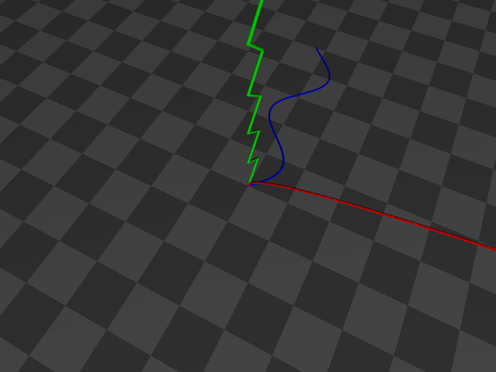
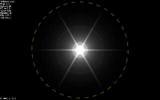
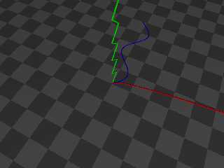
That's a little snippet from a mammoth .pov file, so below is a self-contained
script that you can read and play with. A different function is graphed along
each axis without having to specify each axis operation by hand.
------------------------------------------------------------------------------
// Scene file for demonstrating the use of the dot product for
// extracting the relevant vector component of a macro argument
// by converting it to an index value for direct use in select ()
// Bill "Bald Eagle" Walker 2026/03/21
// There are other ways to do this, but this highlights one of the
// MANY uses of the vector dot product.
#version version;
global_settings {assumed_gamma 1.0}
camera {
location <1/4, 1, -1/2>*15
right x*image_width/image_height
up y
look_at <0, 0, 0>
}
light_source {<40, 30, -50> rgb 1 shadowless}
sky_sphere {pigment {rgb 1}}
plane {y, 0 pigment {checker rgb 0.1 rgb 0.2} scale 2}
#declare E = 0.000001;
#declare Line = 0.05;
#declare Extent = 10;
#declare Step = 0.1;
#declare Vdot = function (Vx, Vy, Vz, Cx, Cy, Cz) {Vx*Cx + Vy*Cy + Vz*Cz}
#macro DotProduct (V1, V2)
#local V1x = V1.x;
#local V1y = V1.y;
#local V1z = V1.z;
#local V2x = V2.x;
#local V2y = V2.y;
#local V2z = V2.z;
Vdot (V1x, V1y, V1z, V2x, V2y, V2z)
#end
#declare even = function(x) {select(mod(x, 2), 0, 1, 0)}
#declare odd = function(x) {select(mod(x, 2), 1, 0, 1)}
#declare Cardinal = array {x, y, z}
#declare Selector = <-1, 0, 1>;
#local ZeroVector = <0, 0, 0>;
#declare FunctionX = function (N) {sqrt(N)}
#declare FunctionY = function (N) {abs(-odd(floor(N))+mod(N, 1))}
#declare FunctionZ = function (N) {sin (N)}
#declare V3 = function (N) {mod (N, 3)}
#declare AxisFunction = function (Switch, N) {
select (
Switch,
FunctionX (N),
FunctionY (N),
FunctionZ (N)
)
}
#for (Axis, 0, 2)
#local Vector = Cardinal [Axis];
//===============================================
#local Component = DotProduct (Vector, Selector);
//===============================================
#local Abscissa = Vector;
#local Ordinate = Cardinal [V3(Axis+1)];
union {
#for (i, 0, Extent, Step)
#local Value = AxisFunction (Component, i);
#local A = Abscissa * i;
#local O = Ordinate * Value;
#local Current = A + O + ZeroVector;
sphere {Current, Line}
#if (i > 0)
cylinder {Last, Current+E Line}
#end
#local Last = Current;
#end
pigment {rgb Vector}
}
#end
Post a reply to this message
Attachments:
Download 'axisselection.png' (55 KB)
Preview of image 'axisselection.png'
|
|
| |
| |
|
|
|
|
| |
| |
|
|
hi,
"Bald Eagle" <cre### [at] netscapenet> wrote:
> OK "POV-Ray community,"
>
> Let's make a concerted effort to get some of those things out of your heads and
> off of your hard drives and onto the forum during the next week.
>
> Post something. It doesn't matter what it is.
> Really. Just post it. Here.
good "initiative", thanks. so, in the spirit :-), attached a "beta" version of
a POV-Ray documentation tool I'm playing with. it requires version 3.7.0.8
documentation (the HTML files) installed, and a GNU/Linux "box"; Tcl, SQLite3,
BASH. while I have a 3.8 version too, the code will need revising first to
allow choice of version (at runtime).
enjoy, jr.
Post a reply to this message
Attachments:
Download 'prdq37b.tar.gz' (923 KB)
|
|
| |
| |
|
|
|
|
| |
| |
|
|
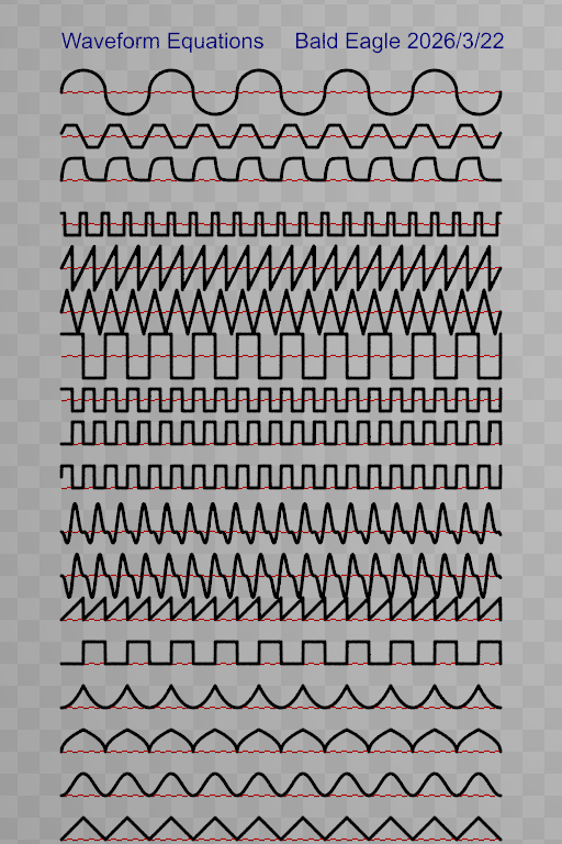
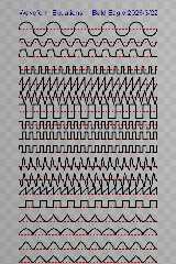
I have a small library of periodic waveforms.
Note that it's a practical library, sometimes with different ways of
implementing the same general shape.
Some could be trimmed down.
Some could be expanded by adding named parameters that control the shape.
Having differentiable curves would be useful for people who have need for, and
know what they're doing with that sort of thing.
I know that there are a lot of "smoothing functions" out there for use in
animations,
There are some nice polar equations out there.
These should all be standard tools that we can easily implement in scenes.
// Waveform Equations
// Bill "Bald Eagle" Walker 2026/3/22
#version version;
global_settings {assumed_gamma 1.0}
#declare Zoom = 20;
camera {
orthographic
location <10, 19, -50>
right x*image_width/Zoom
up y*image_height/Zoom
look_at <10, 19, 0>
}
light_source {<40, 30, -50> rgb 1 shadowless}
sky_sphere {pigment {rgb 1}}
plane {z, 0.01 pigment {checker rgb 0.9 rgb 0.8}}
#declare Axes =
union {
#declare Line = 0.05;
#declare Base = Line*2;
#declare Length = 10;
#declare Ext = 0.25;
cylinder {<0, 0, 0>, <Length, 0, 0>, Line pigment {rgb x}}
cone {<Length, 0, 0>, Base, <Length+Ext, 0, 0>, 0 pigment {rgb x} }
cylinder {<0, 0, 0>, <0, Length, 0>, Line pigment {rgb y}}
cone {<0, Length, 0>, Base, <0, Length+Ext, 0>, 0 pigment {rgb y}}
cylinder {<0, 0, 0>, <0, 0, Length>, Line pigment {rgb z}}
cone {<0, 0, Length>, Base, <0, 0, Length+Ext>, 0 pigment {rgb z}}
}
//object {Axes}
#declare E = 1e-9;
#declare Inf = 1e10;
#declare Line = 0.08;
#declare Extent = 20;
#declare Step = 0.01;
#declare even = function(N) {select(mod(N, 2), 0, 1, 0)}
#declare odd = function(N) {select(mod(N, 2), 1, 0, 1)}
#declare sgn = function(N) {select(N, -1, 0, 1)}
#declare cot = function (N) {1/tan(N)}
#declare sec = function (N) {1/cos(N)}
#declare csc = function (N) {select (sin(N), 1/sin(N), Inf, 1/sin(N))}
#declare Amplitude = 1;
#declare Period = 1;
#declare a = 1;
#declare b = 1;
#declare c = 0;
#declare f = 1;
#declare m = 1;
#declare l = 1;
#declare p = 1;
#declare T = 0.3; // how long pulse wave stays at 1
// capacitor charge-discharge
//
https://www.syncad.com/waveform_block_equations_for_timing_diagram_editors.htm
#declare pns = 0.2;
#declare pps = pns * 10;
#declare rcns = 0.01;
#declare rcps = 10 * rcns;
#declare Sample = function (N) {mod(N, pps/2)}
#declare Charge = function (N) {select (mod(floor(N/(pps/2)),2), 1, 0, 1)}
#declare Waveforms = array {
function (N) {abs(-odd(floor(N))+mod(N, 1))},
function (N) {1-(cos(N*pi)*0.5+0.5)},
function (N) {sqrt(abs(-odd(floor(N))+mod(N, 1)) )},
function (N) {pow(abs(-odd(floor(N))+mod(N, 1)), 2)},
function (N) {select (mod(N, 2)-1, 0, 1)},
function (N) {mod (N, 1)},
function (N) {(-3*pow(sin(N*3), 2)*sin(N*6))*0.5},
function (N) {-pow(sin(N*3), 2)*(a*cos(N*6) + b*sin(N*6))},
//function (N) {-cos(N*3)*(cos(N*6)+sin(N*6))},
function (N) {sgn (sin (2*pi*f*N))/2+0.5},
function (N) {-(2*floor(f*N)-floor(2*f*N))},
function (N) {pow (-1, floor(2*f*N))/2},
function (N) {(2/pi) * atan (tan (pi*f*N/2)) + (2/pi) * atan (cot (pi*f*N/2))},
function (N) {(4/p)*(N-(p/2)*floor(2*N/p+0.5))*pow(-1,floor(2*N/p+0.5))},
function (N) {2*(N/p-floor(0.5+N/p))},
function (N) {sgn (cos(2*pi*N/p)-cos(pi*T/p)) * 0.5},
function (N) {select (Charge(N), 0, a*(1-exp(-Sample(N)/rcps)),
a*exp(-Sample(N)/rcps) )},
function (N) {(a/pi) * (asin(sin((pi/m)*N+l)) + acos(cos((pi/m)*N+l))) - (a/2)
+ c},
function (N) {pow(-1, floor(N/2))*sqrt (1-pow((mod(N,2)-1),2))}
};
#declare NF = dimension_size (Waveforms, 1)-1;
#declare Abscissa = x;
#declare Ordinate = y;
// Applicate: The z-coordinate (the last of the three terms by which a point is
referred to,
// in a system of Cartesian coordinates for a three-dimensional space)
#local ZeroVector = <0, 0, 0>;
#for (F, 0, NF)
#ifdef(Function) #undef Function #end
#local Function = Waveforms [F];
//#debug concat ("F = ", str(F, 0, 0), "\n")
#local Shift_Y = y*F*2;
cylinder {<0, F*2, 0>, <Extent, F*2, 0> Line*0.75 pigment {checker rgb x rgbf 1
scale 0.25}}
union {
#for (i, 0, Extent, Step)
#local Value = Function (i);
#local A = Abscissa * i;
#local O = Ordinate * Value + Shift_Y;
#local Current = A + O + ZeroVector;
sphere {Current, Line}
#if (i > 0)
cylinder {Last, Current+E Line}
#end
#local Last = Current;
#end
pigment {rgb 0}
}
#end
text { ttf "arial.ttf", "Waveform Equations Bald Eagle 2026/3/22", 0.02, 0.0
pigment {rgb z*0.4} translate y*(F)*2}
Post a reply to this message
Attachments:
Download 'waveforms.png' (145 KB)
Preview of image 'waveforms.png'
|
|
| |
| |
|
|
|
|
| |
| |
|
|
On 3/20/2026 4:21 PM, Bald Eagle wrote:
> OK "POV-Ray community,"
>
> Let's make a concerted effort to get some of those things out of your heads and
> off of your hard drives and onto the forum during the next week.
>
> Post something. It doesn't matter what it is.
> Really. Just post it. Here.
>
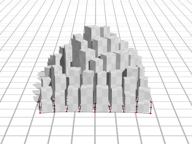
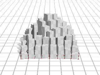
I've been on-and-off playing with creating cities on the irregular grids
I was playing with last year.
Buildings align to the "roads" defined by the grid.
Post a reply to this message
Attachments:
Download 'fillrect.png' (66 KB)
Preview of image 'fillrect.png'
|
|
| |
| |
|
|
|
|
| |
| |
|
|
"Bald Eagle" <cre### [at] netscapenet> wrote:
> Post something. It doesn't matter what it is.
> Really. Just post it. Here.
>
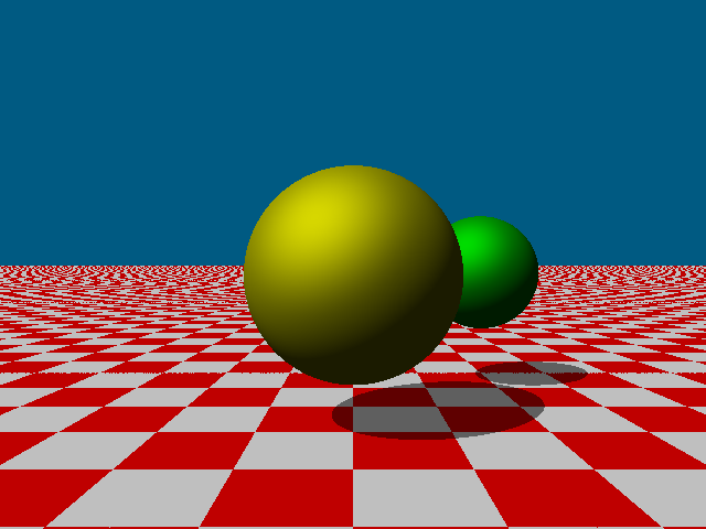
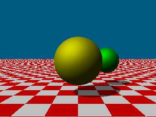
I'm modifying a compiler I wrote that was for an assignment in my compilers
college course many years ago. I've expanded the grammar to be a fully usable
language rather than a "toy" language. So, of course, I just had to create a
raytracer for it. Here's the source code written in my language:
{
/* Integer loop + shading vars */
i_x = 0; i_y = 0;
i_shade = 0;
i_check = 0;
i_mod2 = 0;
/* Camera origin */
f_sx = 0.0; f_sy = 0.1; f_sz = 5.5;
/* Light direction (will normalize) */
#f_lx = -2.0; f_ly = 3.0; f_lz = -1.0;
f_lx = -2.0; f_ly = 3.0; f_lz = 2.0;
/* Ray direction */
f_dx = 0.0; f_dy = 0.0; f_dz = 0.0;
/* 2nd Sphere position */
f_sp_x = 1.75; f_sp_y = 0.0; f_sp_z = -2.0;
/* Sphere radiuses */
f_sp1_r = 1.2; f_sp2_r = 0.6;
/* Sphere intersection */
f_b = 0.0; f_c = 0.0; f_disc = 0.0; f_t = 0.0;
/* plane height */
f_ply = -1.6;
/* Normals and points */
f_nx = 0.0; f_ny = 0.0; f_nz = 0.0;
f_px = 0.0; f_py = 0.0; f_pz = 0.0;
/* Helpers */
f_len = 0.0; f_dot = 0.0; f_spec = 0.0; f_tmp = 0.0;
f_fx = 0.0; f_fz = 0.0;
/* Shadow ray vars */
f_sdx = 0.0; f_sdy = 0.0; f_sdz = 0.0;
f_tb = 0.0; f_tc = 0.0; f_tdisc = 0.0; f_tshadow = 0.0;
/* Normalize light direction once */
f_len = sqrt(f_lx*f_lx + f_ly*f_ly + f_lz*f_lz);
f_lx = f_lx / f_len; f_ly = f_ly / f_len; f_lz = f_lz / f_len;
f_aspect = 1.0;
print "P6\n640 480\n255\n";
/* Image loop */
for i_y = -240 to 239 do
{
for i_x = -320 to 319 do
{
/* Ray direction from camera through pixel */
f_dx = float(i_x) / 490.0;
f_dy = -float(i_y) * f_aspect / 490.0;
f_dz = -1.0;
/* Normalize ray direction */
f_len = sqrt(f_dx*f_dx + f_dy*f_dy + f_dz*f_dz);
f_dx = f_dx / f_len;
f_dy = f_dy / f_len;
f_dz = f_dz / f_len;
/* Sphere intersection: center at (0,0,0), radius 1.2 */
f_tx = f_sx;
f_ty = f_sy;
f_tz = f_sz;
f_b = 2.0 * (f_dx*f_tx + f_dy*f_ty + f_dz*f_tz);
f_c = f_tx*f_tx + f_ty*f_ty + f_tz*f_tz - f_sp1_r;
f_disc = f_b*f_b - 4.0*f_c;
if f_disc >= 0.0 then
{
/* Hit sphere: nearest t */
f_t = (-f_b - sqrt(f_disc)) / 2.0;
if f_t <= 0.0 then
{
/* Behind camera: treat as no sphere hit, fall through */
f_disc = -1.0;
}
else
{
f_obj_red = 0.9;
f_obj_green = 0.9;
f_obj_blue = 0.0;
}
}
/* Sphere intersection: center at (f_sp_x,f_sp_y,f_sp_z), radius .6 */
f_tx2 = f_sx - f_sp_x;
f_ty2 = f_sy - f_sp_y;
f_tz2 = f_sz - f_sp_z;
f_b = 2.0 * (f_dx*f_tx2 + f_dy*f_ty2 + f_dz*f_tz2);
f_c = f_tx2*f_tx2 + f_ty2*f_ty2 + f_tz2*f_tz2 - f_sp2_r;
f_disc2 = f_b*f_b - 4.0*f_c;
if f_disc2 >= 0.0 then
{
/* Hit sphere: nearest t */
f_t2 = (-f_b - sqrt(f_disc2)) / 2.0;
if f_t2 > 0.0 then
{
b_sp1=(f_disc<0.0); #(f_t<0.0); /* boolean */
b_sp2=(f_t2<f_t); /* boolean */
if b_sp1+b_sp2 then /* boolean + = or */
{
f_obj_red = 0.0;
f_obj_green = 0.9;
f_obj_blue = 0.0;
f_disc = f_disc2;
f_t = f_t2;
f_tx = f_tx2;
f_ty = f_ty2;
f_tz = f_tz2;
}
}
}
if f_disc < 0.0 then
{
/* No sphere hit: try ground plane y = -1.6 */
if f_dy == 0.0 then
{
/* Ray parallel to plane: background */
printc 0;
printc 90;
printc 130;
}
else
{
f_t = (f_ply - f_sy) / f_dy;
if f_t <= 0.0 then
{
/* Plane behind camera */
printc 0;
printc 90;
printc 130;
}
else
{
/* Hit point on plane */
f_px = f_sx + f_dx*f_t;
f_py = f_ply;
f_pz = f_sz + f_dz*f_t;
/* Checkerboard: floor(px), floor(pz) using int */
f_fx = float(int(f_px));
if f_px < 0.0 then f_fx = f_fx - 1.0;
f_fz = float(int(f_pz));
if f_pz < 0.0 then f_fz = f_fz - 1.0;
i_check = (int(f_fx + f_fz)) % 2;
if (i_check == 0) then { f_red=0.75; f_green=0.0; f_blue=0.0; }
else { f_red=0.75; f_green=0.75; f_blue=0.75; }
/* Shadow from sphere onto plane:
cast ray from plane point toward light,
check if it hits sphere before light. */
f_sdx = f_lx;
f_sdy = f_ly;
f_sdz = f_lz;
/* Sphere intersection from plane point:
ray: P + t*L, sphere at origin, radius 1 */
f_tb = 2.0 * (f_sdx*f_px + f_sdy*f_py + f_sdz*f_pz);
f_tc = f_px*f_px + f_py*f_py + f_pz*f_pz - f_sp1_r;
f_tdisc = f_tb*f_tb - 4.0*f_tc;
if f_tdisc > 0.0 then
{
f_tshadow = (-f_tb - sqrt(f_tdisc)) / 2.0;
if f_tshadow > 0.0 then
{
/* In shadow: darken */
f_red = f_red * 0.5;
f_green = f_green * 0.5;
f_blue = f_blue * 0.5;
}
}
f_tx = f_px - f_sp_x;
f_ty = f_py - f_sp_y;
f_tz = f_pz - f_sp_z;
f_tb = 2.0 * (f_sdx*f_tx + f_sdy*f_ty + f_sdz*f_tz);
f_tc = f_tx*f_tx + f_ty*f_ty + f_tz*f_tz - f_sp2_r;
f_tdisc = f_tb*f_tb - 4.0*f_tc;
if f_tdisc > 0.0 then
{
f_tshadow = (-f_tb - sqrt(f_tdisc)) / 2.0;
if f_tshadow > 0.0 then
{
/* In shadow: darken */
f_red = f_red * 0.5;
f_green = f_green * 0.5;
f_blue = f_blue * 0.5;
}
}
i_red=int(f_red * 255.0);
i_green=int(f_green * 255.0);
i_blue=int(f_blue * 255.0);
if i_red < 0 then i_red = 0;
if i_red > 255 then i_red = 255;
if i_green < 0 then i_green = 0;
if i_green > 255 then i_green = 255;
if i_blue < 0 then i_blue = 0;
if i_blue > 255 then i_blue = 255;
printc i_red;
printc i_green;
printc i_blue;
}
}
}
else
{
/* Sphere shading */
/* Hit point */
f_px = f_tx + f_dx*f_t;
f_py = f_ty + f_dy*f_t;
f_pz = f_tz + f_dz*f_t;
/* Normal at sphere */
f_nx = f_px;
f_ny = f_py;
f_nz = f_pz;
f_len = sqrt(f_nx*f_nx + f_ny*f_ny + f_nz*f_nz);
f_nx = f_nx / f_len;
f_ny = f_ny / f_len;
f_nz = f_nz / f_len;
/* Diffuse term */
f_dot = f_nx*f_lx + f_ny*f_ly + f_nz*f_lz;
if f_dot < 0.0 then f_dot = 0.0;
/* Specular: reflection of light around normal, dotted with view dir (-ray)
*/
f_tmp = 2.0 * f_dot;
f_fx = f_tmp*f_nx - f_lx;
f_fz = f_tmp*f_nz - f_lz;
f_len = f_tmp*f_ny - f_ly; /* reuse f_len as ry */
/* view dir is -ray: (-dx, -dy, -dz) */
f_spec = f_fx*(-f_dx) + f_len*(-f_dy) + f_fz*(-f_dz);
if f_spec < 0.0 then f_spec = 0.0;
f_spec = f_spec * f_spec;
/* Combine diffuse + specular + small ambient */
f_dot = 0.12 + .6*f_dot + 0.3*f_spec;
if f_dot < 0.0 then f_dot = 0.0;
if f_dot > 1.0 then f_dot = 1.0;
i_red = int(f_obj_red * f_dot * 255.0);
i_green = int(f_obj_green * f_dot * 255.0);
i_blue = int(f_obj_blue * f_dot * 255.0);
if i_red < 0 then i_red = 0;
if i_red > 255 then i_red = 255;
if i_green < 0 then i_green = 0;
if i_green > 255 then i_green = 255;
if i_blue < 0 then i_blue = 0;
if i_blue > 255 then i_blue = 255;
printc i_red;
printc i_green;
printc i_blue;
}
}
}
}
There are no specific variable type declarations. The type is based on the
first letter of the variable (i for integer, f for floating point, s for string,
and b for boolean).
# are line comments and /* */ are comment blocks. The resulting compiled
x86/x64 program (either Windows or Linux) outputs a PPM (netpbm) image file.
The code is not that great because I haven't fully implemented functions (so no
recursion), and there's no pointers, no structs, and no arrays. Here's the
resulting image:
Post a reply to this message
Attachments:
Download 'rayout.png' (18 KB)
Preview of image 'rayout.png'
|
|
| |
| |
|
|
|
|
| |
|
|