|
|
|
|
|
|
| |
| |
|
|
|
|
| |
| |
|
|
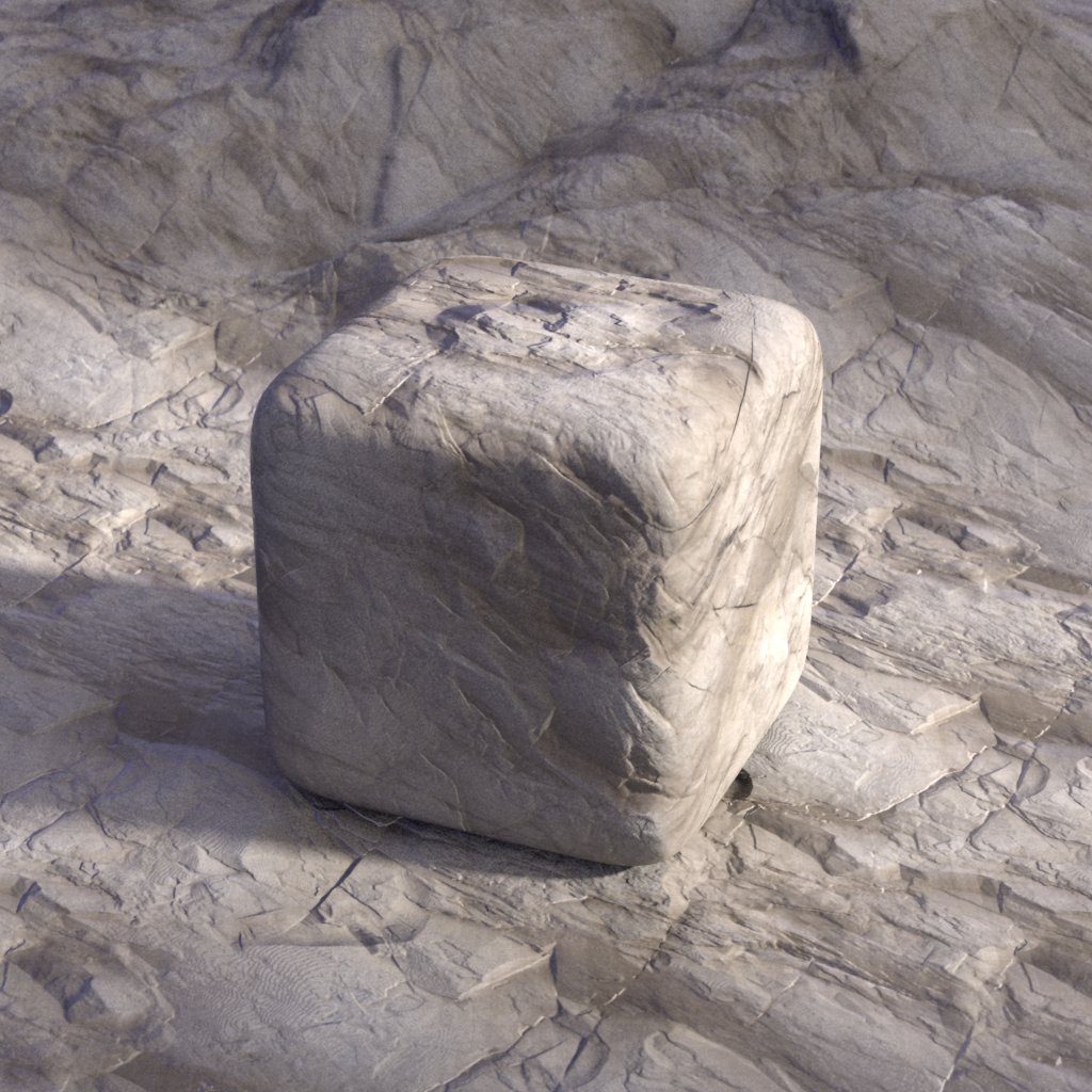
Hi,
The attached image is a preliminary test using both a color map and a
displacement map I found online of some rocks. Scene objects are: plane;
superellipsoid; and a height_field.
Here's a simple triplanar mapping macro:
#macro Triplanar(Pigment)
pigment_pattern{
slope x
triangle_wave
}
pigment_map{
[0 Pigment rotate y*90]
[1
pigment_pattern{
slope y
triangle_wave
}
pigment_map{
[0 Pigment rotate x*90 translate z*2]
[1 Pigment rotate z*165 translate x*2]
}
]
}
#end
It's invoked it like this:
pigment_pattern{Triplanar(Pigment)}
where 'Pigment' is a 2D pigment oriented along the z axis (e.g. default image
map). You can invoke it the same way in pigment, normal or texture blocks.
Sam
Post a reply to this message
Attachments:
Download 'triplanar6m_02s.jpg' (193 KB)
Preview of image 'triplanar6m_02s.jpg'
|
|
| |
| |
|
|
|
|
| |
| |
|
|
"Samuel B." <stb### [at] hotmail com> wrote:
> triplanar mapping
Attached is the same scene with some things changed. Here's the texture I used:
texture{
pigment{
average
pigment_map{
[1 Triplanar(PImgCol)]
[1
pigment_pattern{Triplanar(PImgDisp)}
color_map{
[0 rgb .75*<.25, .2, .15>]
[.5 rgb <.5, .4, .3>]
[1 rgb 1]
}
]
}
}
normal{
pigment_pattern{Triplanar(PImgDisp)}
bump_size 2
accuracy 7/1024
}
}
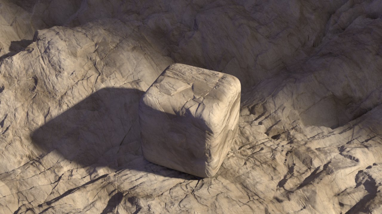
'PImgCol' is the color map, and 'PImgDisp' is the displacement map. (The hf
isn't very high res, since it uses a displacement map which is only 8-bit, and
would therefore produce stair-stepping artifacts at higher hf resolutions).
Sam com> wrote:
> triplanar mapping
Attached is the same scene with some things changed. Here's the texture I used:
texture{
pigment{
average
pigment_map{
[1 Triplanar(PImgCol)]
[1
pigment_pattern{Triplanar(PImgDisp)}
color_map{
[0 rgb .75*<.25, .2, .15>]
[.5 rgb <.5, .4, .3>]
[1 rgb 1]
}
]
}
}
normal{
pigment_pattern{Triplanar(PImgDisp)}
bump_size 2
accuracy 7/1024
}
}
'PImgCol' is the color map, and 'PImgDisp' is the displacement map. (The hf
isn't very high res, since it uses a displacement map which is only 8-bit, and
would therefore produce stair-stepping artifacts at higher hf resolutions).
Sam
Post a reply to this message
Attachments:
Download 'triplanar26m_11s.jpg' (153 KB)
Preview of image 'triplanar26m_11s.jpg'

|
|
| |
| |
|
|
|
|
| |
| |
|
|
Op 15-1-2024 om 01:44 schreef Samuel B.:
> "Samuel B." <stb### [at] hotmailcom> wrote:
>> triplanar mapping
>
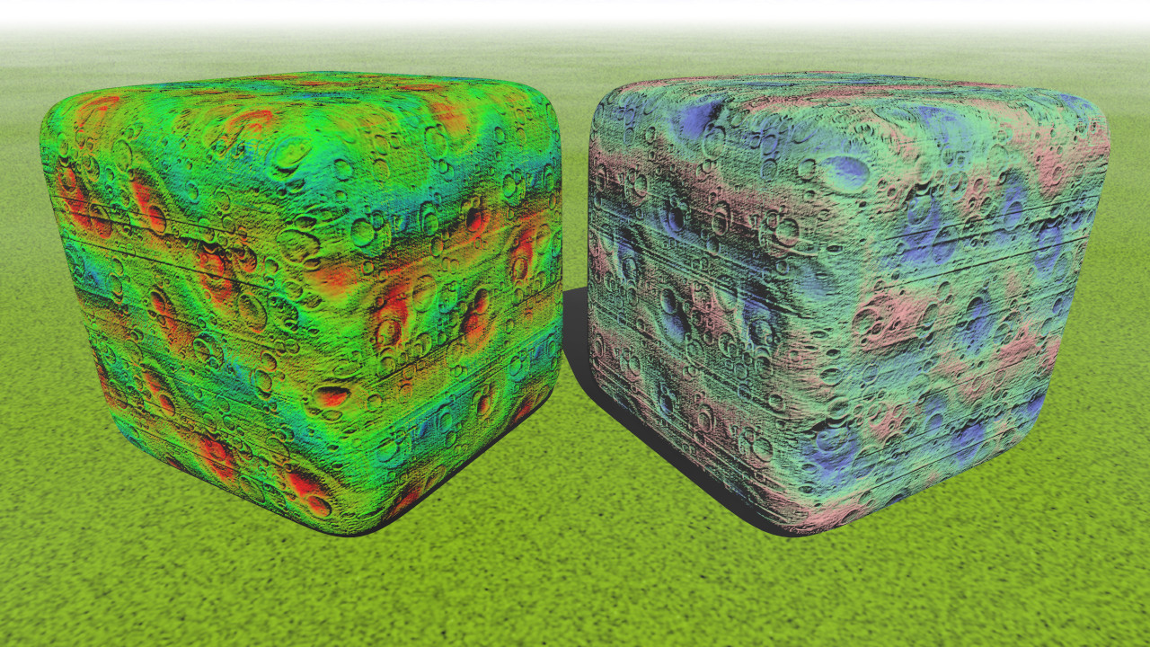
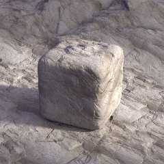
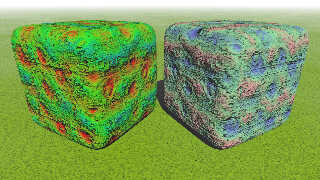
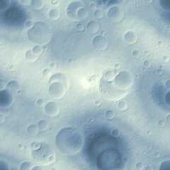
Very good!
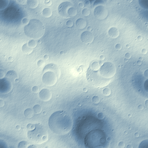
This is what I get with a rapid test of your code. Also attached is the
crater map I use.
--
Thomas
Post a reply to this message
Attachments:
Download 'sb_triplanar mapping.jpg' (522 KB)
Download 'craters.png' (274 KB)
Preview of image 'sb_triplanar mapping.jpg'
Preview of image 'craters.png'
|
|
| |
| |
|
|
|
|
| |
| |
|
|
Op 15-1-2024 om 14:48 schreef Thomas de Groot:
> Op 15-1-2024 om 01:44 schreef Samuel B.:
>> "Samuel B." <stb### [at] hotmailcom> wrote:
>>> triplanar mapping
>>
>
> Very good!
>
> This is what I get with a rapid test of your code. Also attached is the
> crater map I use.
>
Forgot to say: left is your first code, right is the second one.
--
Thomas
Post a reply to this message
|
|
| |
| |
|
|
|
|
| |
| |
|
|
Thomas de Groot <tho### [at] degrootorg> wrote:
> Op 15-1-2024 om 01:44 schreef Samuel B.:
> > "Samuel B." <stb### [at] hotmailcom> wrote:
> >> triplanar mapping
> >
>
> Very good!
>
> This is what I get with a rapid test of your code. Also attached is the
> crater map I use.
>
> --
> Thomas
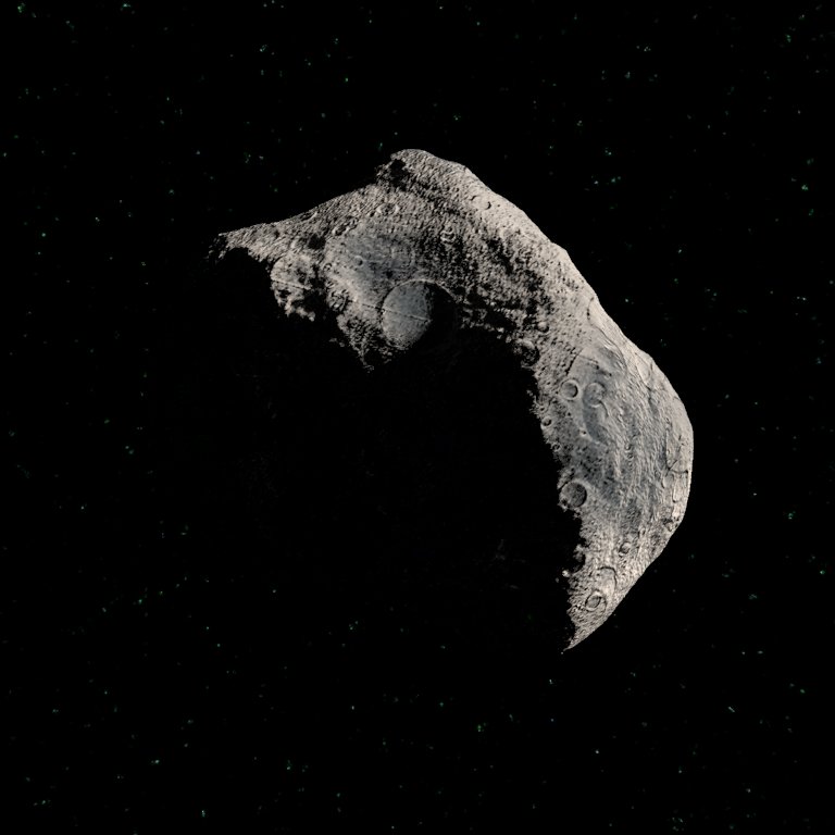
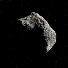
Hmm, I don't know what's causing those parallel lines, but it might be the lack
of a sharpness value. I updated the macro, and its new sharpness input /should/
help mitigate such errors plus any warping caused planar mapping. Also, that
crater map has some issues... not sure what the problem is. The attached is a
test render I made today, and the code below is what produced it.
Sam
/*
triplanar-craters-test.pov
2024 stb
+fn +f +a0.3 +am2 +r2 +w768 +h768
*/
#version 3.7;
#default{ finish{ambient 0} }
global_settings{
assumed_gamma 1.0
#if(true)
radiosity{
pretrace_end .04
count 32
error_bound .25
recursion_limit 1
nearest_count 10
normal on
}
#end
}
camera{
right x up y
location -z*1000
look_at 0
scale .0027
}
// sunlight
#if(true)
light_source{
<1, .5, 0>*1e5, srgb <1.5, 1.4, 1.3>
#if(true)
#declare ALRes = 2;
#declare ALSize = .06*1e5;
area_light x*ALSize, z*ALSize, ALRes, ALRes
jitter
adaptive 1
area_illumination
#end
}
#end
// starry background
#if(true)
sky_sphere{
pigment{
granite
scale .05
poly_wave 32
pigment_map{
[0 rgb 0]
[.25 bozo scale .01]
}
}
}
#end
// some triplanar mapping settings
#declare TriplanarScale = 1.5; // triplanar image scaling
#declare TriplanarTranslate = <0, .25, 0>; // triplanar image translation
#declare TriplanarAccuracy = 1.0; // accuracy of triplanar surface normals
(1=default; higher=smoother)
#declare TriplanarSharpness = 0.7; // 0 to 1
// input image for triplanar color and normal
#declare PImg =
pigment{
image_map{
png "craters.png"
interpolate 2
}
scale TriplanarScale
}
// try to find a proper normal accuracy value based on TriplanarScale and image
size
#declare ImageRes = max_extent(PImg);
#declare ImageRes = min(ImageRes.x, ImageRes.y);
// isosurface displacement
#declare FDisp =
function{
pattern{
bumps
scale .65
turbulence .3
translate 2.5*z
}
}
// triplanar macro (Pigment in z-direction; Sharpness value between 0 and 1)
#macro Triplanar(Pigment, Sharpness)
pigment_pattern{
slope x
triangle_wave
}
pigment_map{
[0+.5*Sharpness Pigment rotate y*90]
[1-.5*Sharpness
pigment_pattern{
slope y
triangle_wave
}
pigment_map{
[0+.5*Sharpness Pigment rotate x*90]
[1-.5*Sharpness Pigment rotate z*165]
}
]
}
translate TriplanarTranslate
#end
// asteroid
isosurface{
function{
sqrt(x*x+y*y+z*z)
-.5*FDisp(x, y, z)
-.5
}
accuracy .001
max_gradient 1.54
texture{
pigment{
pigment_pattern{Triplanar(PImg, TriplanarSharpness)}
color_map{
[0 rgb <0, .05, .1>]
[1 rgb 1]
}
}
normal{
pigment_pattern{Triplanar(PImg, TriplanarSharpness)}
poly_wave .5
bump_size .75
accuracy TriplanarAccuracy / ImageRes
}
}
}
Post a reply to this message
Attachments:
Download 'triplanar-craters-test0m_28s.jpg' (47 KB)
Preview of image 'triplanar-craters-test0m_28s.jpg'
|
|
| |
| |
|
|
|
|
| |
| |
|
|
Op 16-1-2024 om 02:22 schreef Samuel B.:
> Thomas de Groot <tho### [at] degrootorg> wrote:
>> Op 15-1-2024 om 01:44 schreef Samuel B.:
>>> "Samuel B." <stb### [at] hotmailcom> wrote:
>>>> triplanar mapping
>>>
>>
>> Very good!
>>
>> This is what I get with a rapid test of your code. Also attached is the
>> crater map I use.
>>
>> --
>> Thomas
>
> Hmm, I don't know what's causing those parallel lines, but it might be the lack
> of a sharpness value. I updated the macro, and its new sharpness input /should/
> help mitigate such errors plus any warping caused planar mapping. Also, that
> crater map has some issues... not sure what the problem is. The attached is a
> test render I made today, and the code below is what produced it.
>
> Sam
>
>
Right. I was wondering about those lines too and I assumed they were
somehow generated by the places were the three planes /joined/. I am
wondering now if there might nor be a problem with the seamless (?)
joints of the crater map. going to investigate...
--
Thomas
Post a reply to this message
|
|
| |
| |
|
|
|
|
| |
| |
|
|
Op 16-1-2024 om 10:15 schreef Thomas de Groot:
> Right. I was wondering about those lines too and I assumed they were
> somehow generated by the places were the three planes /joined/. I am
> wondering now if there might nor be a problem with the seamless (?)
> joints of the crater map. going to investigate...
>
No. looks like that is fine.
--
Thomas
Post a reply to this message
Attachments:
Download 'hf_seamless_test.jpg' (382 KB)
Preview of image 'hf_seamless_test.jpg'
|
|
| |
| |
|
|
|
|
| |
| |
|
|
"Samuel B." <stb### [at] hotmailcom> wrote:
> Hmm, I don't know what's causing those parallel lines, but it might be the lack
> of a sharpness value. I updated the macro, and its new sharpness input /should/
> help mitigate such errors plus any warping caused planar mapping.
So, they way I understood it was that each plane contributed to the texturing of
the surface by how closely its normal matched that of the surface. Surfaces
with a 45 deg angle would be an even blend of 2 planes, etc.
I think you have the idea properly implemented in code, but you should eliminate
the unnecessary triangular_wave statement? Shouldn't it be a straight sawtooth
wave?
It's early and I might be reading it wrong, but should the slope {x} pattern
blend between an xz plane and one rotated into the yz plane by rotation around
z? (first pigment map), etc? Seems you have that first image map rotated around
y, when it ought to be rotated around x to make it lay flat.
Then rotate around z, then y to cover all 3 planes.
"The slope value at a given point is dependent on the angle between the
<Direction> vector and the normal of the surface at that point."
- BW
Post a reply to this message
|
|
| |
| |
|
|
|
|
| |
| |
|
|
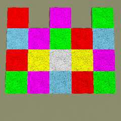
I got a really strange problem applying your code to:
superellipsoid {
<0.25,0.25>
texture {
pigment {
pigment_pattern {Triplanar(PImg, TriplanarSharpness)}
color_map {
[0.20 rgb <1,1,0>]
[0.50 rgb <1,0,1>]
[0.80 rgb <0,1,1>]
}
}
normal {
pigment_pattern {Triplanar(PImg, TriplanarSharpness)}
poly_wave .5
bump_size .75*2
accuracy TriplanarAccuracy / ImageRes
}
}
scale 0.75
rotate <0, 30, 0>
translate <0, 0.75, 0>
}
If you change the rotation of the object, especially > 30*y or < -30*y
in this example, the texture becomes distorted! Also with other types of
objects.
What is happening here?
--
Thomas
Post a reply to this message
|
|
| |
| |
|
|
|
|
| |
| |
|
|
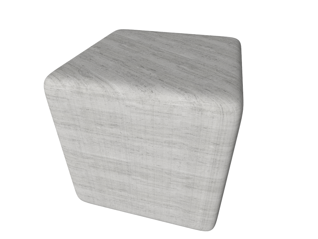
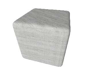
I gave it a go, since I had to visualize the rotations, lest it bother me for
the rest of the day. I use a helper macro to choose the waveform, and cubic
seemed to work really nicely. I'd suggest trying it with different images to
see if the smoothness is a result of just using one test image.
Rotating the superellipsoid doesn't seem to have too much effect - the line
artefacts might be more to do with the linear travertine image?
- BW
#declare IM = pigment {image_map { "YourImage.png" interpolate 2}}
#macro WaveType (N)
#switch (N)
#case (0)
ramp_wave
#break
#case (1)
triangle_wave
#break
#case (2)
sine_wave
#break
#case (3)
scallop_wave
#break
#case (4)
cubic_wave
#break
#case (5)
poly_wave 0.5
#break
#end
#end
#macro TP (P, N)
pigment {
average
pigment_map {
[ 1.0
pigment_pattern {
slope x
WaveType (N)
}
pigment_map {
// When 100% aligned with x
[0 IM rotate -y*90]
// vector can rotate away from x in either the y or z direction
[ 1.0
pigment_pattern {
// arbitrarily choose z axis for primary pattern
slope z
WaveType (N)
}
pigment_map {
// 100% aligned with z
[0 IM ]
// 100 aligned with y
[1 IM rotate x*90]
}
]
}
]
[ 1.0
pigment_pattern {
slope y
WaveType (N)
}
pigment_map {
// When 100% aligned with y
[0 IM rotate x*90]
// vector can rotate away from x in either the y or z direction
[ 1.0
pigment_pattern {
// arbitrarily choose z axis for primary pattern
slope x
WaveType (N)
}
pigment_map {
// 100% aligned with x
[0 IM rotate -y*90]
// 100 aligned with z
[1 IM]
}
]
}
]
[ 1.0
pigment_pattern {
slope z
WaveType (N)
}
pigment_map {
// When 100% aligned with z
[0 IM]
// vector can rotate away from x in either the y or z direction
[ 1.0
pigment_pattern {
// arbitrarily choose x axis for primary pattern
slope z
WaveType (N)
}
pigment_map {
// 100% aligned with x
[0 IM rotate -y*90]
// 100 aligned with y
[1 IM rotate x*90]
}
]
}
]
}
}
#end
#declare Round = 0.125;
#declare Rounded_Box = superellipsoid { <Round, Round> rotate -y*30}
object {Rounded_Box TP (IM, 3)}
Post a reply to this message
Attachments:
Download 'tpmapping.png' (485 KB)
Preview of image 'tpmapping.png'
|
|
| |
| |
|
|
|
|
| |