|
 |
Re:
http://news.povray.org/povray.general/thread/%3Cweb.5cf316ed57960f354eec112d0%40news.povray.org%3E/
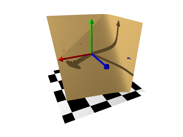
So here's the relevant section.
Little tidbits here are, the equation of a plane is Ax + By + Cz = D,
or Ax + By + Cz - D = 0.
So when you do plane {y, 0} what you're actually doing is
function {0x + 1y + 0z - 0}
I take the 3 points that will define one flat "arm" of the curved sheet and
derive the coefficients for the plane equation from the <x, y, z> coordinates.
The other plane is just a plane defined by a cardinal axis normal (but which
ought to be defined by a vector derive from the 4th point projected onto the
plane.... I'm getting there...
Multiplying the function by -1 gives the equivalent of adding the inverse
keyword.
then I just blob them together like in the documentation for isosurfaces with a
blob threshold of 0.3
#declare Point1 = <3, 0.5, -1>;
#declare Point2 = <1.5, -0.5, 0>;
#declare Point3 = <1, 1, -1>;
#declare Point4 = <-3, 0.125, 3,>; /// odd point out
#declare Z4 = Point4.x;
// derive the plane equation
#declare A1 = Point1.y*(Point2.z-Point3.z) + Point2.y*(Point3.z-Point1.z) +
Point3.y*(Point1.z-Point2.z);
#declare B1 = Point1.z*(Point2.x-Point3.x) + Point2.z*(Point3.x-Point1.x) +
Point3.z*(Point1.x-Point2.x);
#declare C1 = Point1.x*(Point2.y-Point3.y) + Point2.x*(Point3.y-Point1.y) +
Point3.x*(Point1.y-Point2.y);
#declare D1 = -1*(Point1.x*(Point2.y*Point3.z-Point3.y*Point2.z) +
Point2.x*(Point3.y*Point1.z-Point1.y*Point3.z) +
Point3.x*(Point1.y*Point2.z-Point2.y*Point1.z));
#declare Blob_Threshold=0.3;
#declare fn_A = function { -1*(A1*x + B1*y + C1*z - D1)}
#declare fn_B = function { (x - Z4) }
isosurface {
function {
(1+Blob_Threshold)
-pow(Blob_Threshold, fn_A(x,y,z))
-pow(Blob_Threshold, fn_B(x,y,z))
}
open
max_gradient 10
contained_by { box { -4, 4 } }
texture {Tan} interior_texture {Gray}
}
/*isosurface {
function {fn_A(x,y,z)}
//open
contained_by {box {-4, 4}}
texture {Blue} interior_texture {Gray}
}*/
#declare Rad = Line;
sphere {Point1 Rad texture {Red}}
sphere {Point2 Rad texture {Red}}
sphere {Point3 Rad texture {Red}}
sphere {Point4 Rad texture {Blue}}
/*intersection {
plane {<A1, B1, C1>, D1 inverse}
box {-4, 4 texture {pigment {rgbt 1}}}
texture {Green}
interior_texture {pigment {rgbt 1}}
}*/
Not robust or optimized in any way, but it shows proof of concept.
Post a reply to this message
Attachments:
Download 'documentationfigures.png' (76 KB)
Preview of image 'documentationfigures.png'

|
|
|
|
So, a few things I noticed while playing with this some more.
Given any 3 + 1 points (4 th point is always nonplanar, or at least outside of
the triangle) you can "throw them down onto a table" and they will land with 3
points flat down with one either "over there" on the table, or in the air.
All flat = just a plane so we can just always note this and ignore it from now
on.
Then you can take a sheet of paper and bend it upwards and tuck it under the 4th
point so the sheet is between the point and the "table". Obviously you can
shift the paper to get different locations and eccentricities of the bend.
So there are a lot of 2D curves that could be used to fit the task - parabolas,
one side of a hyperbola, some sort of minimum-energy / minimum curvature thing
(picture a sheet of spring steel being shoved under the 4th point and slid under
until the sheet _just_ contacts all 3 points on the table).
On to the current implementation:
I wanted to (for the moment) restrict the way this was constructed to a right
angle between the wings of the fold, and so I needed to get a plane
perpendicular to the plane of the triangle.
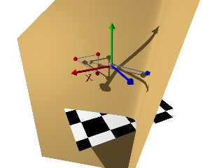
So I computed the centroid, projected the 4th point onto the triangle's plane,
and that gives me a line that lies on that plane - it's parallel and coincident.
But that also means that it's the _normal vector_ to define a plane that's
perpendicular to the triangle's plane. (gray dots and lines)
Super. So now can define that plane, but I need to know what "D" is - the
offset from zero so that it coincides with the 4th point.
So I project the 4th point onto the perpendicular plane, calculate the length of
that vector, and use that length as D.
(more gray dots and lines)
There's still some weirdness going on when I move the 4 points around to get
some tilt to the triangle plane - I lose coplanarity, as you can see by the
shadows cast by the red points.
Maybe I'll get a chance to sift through some more POV-Ray documentation and see
if there are internal functions / include files / vector macros that do what I'm
doing with the analytical geometry equations (I think I got these from Graphics
Gems - dunno)
Post a reply to this message
Attachments:
Download 'documentationfigures.png' (135 KB)
Preview of image 'documentationfigures.png'
|
|