|
|
|
|
|
|
| |
| |
|
|
From: William F Pokorny
Subject: Experimenting with 3.7 cubic warp and df3 based isosurfaces.
Date: 20 Dec 2017 11:25:10
Message: <5a3a8ee6@news.povray.org>
|
|
|
| |
| |
|
|
Back in 3.7 Warp added warp{cubic} for patterns. Helpful in that df3
density_file patterns so warped can be much flatter (smaller in size)
and still result in deeper shapes/medias. Similar to other built in
warps, one needs to offset in +z - after x, y and z normalization(1) -
by the half width you want for the box centered on the origin.
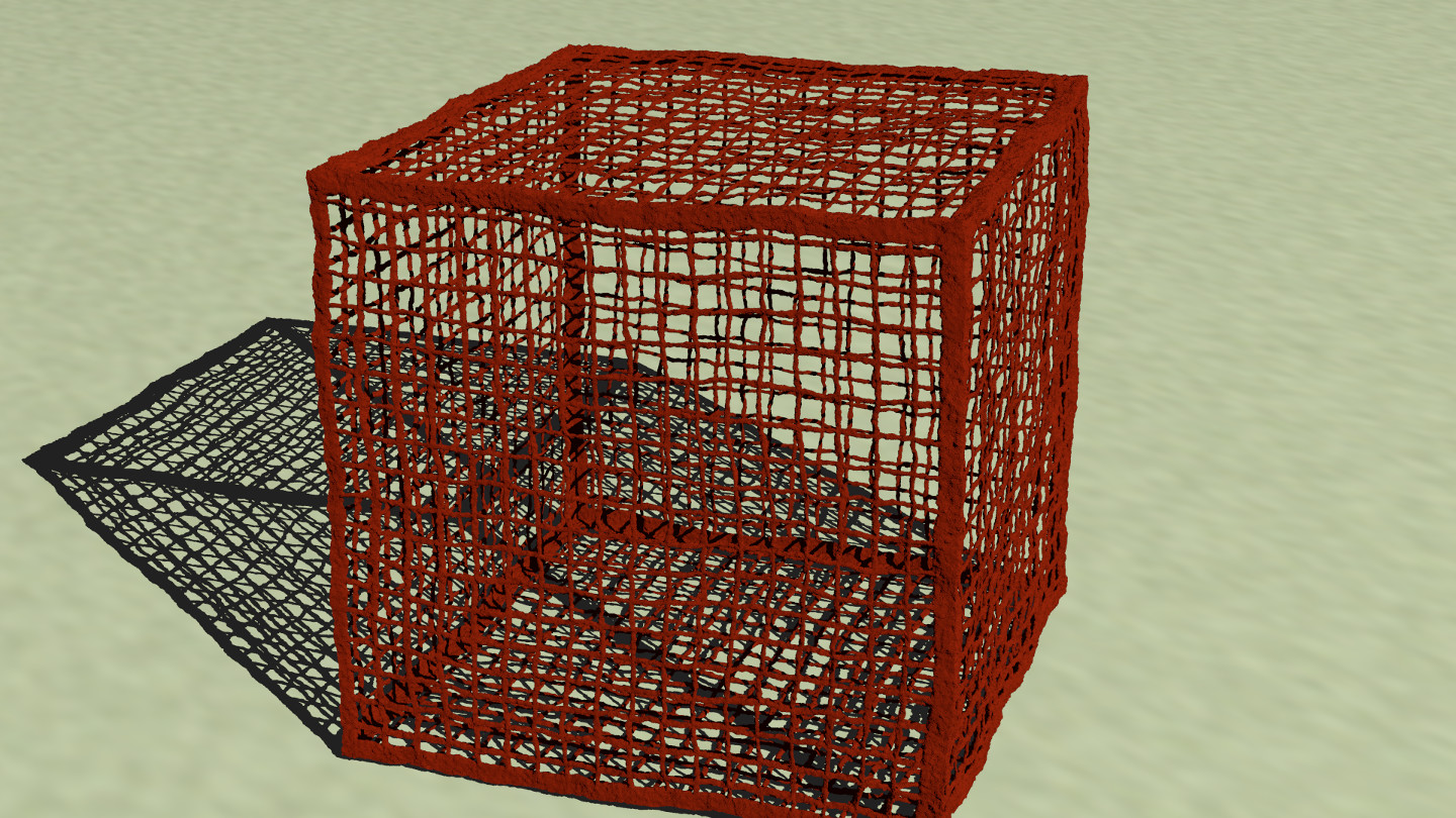
Yep, the isosurface max_gradient for the attached image should have been
set higher.
Bill P.
(1) - As with 2d images and image maps, 3d df3s - no matter their input
dimensions - always fill the unit cube. Before warping one must do a
normalization scale to get the thinner, as intended, 'shape' which is
then offset in +z for size ahead of the warp{cubic}.
Post a reply to this message
Attachments:
Download 'isoboxb.jpg' (482 KB)
Preview of image 'isoboxb.jpg'
|
|
| |
| |
|
|
|
|
| |
| |
|
|
William F Pokorny <ano### [at] anonymous org> wrote:
> Back in 3.7 Warp added warp{cubic} for patterns. Helpful in that df3
> density_file patterns so warped can be much flatter (smaller in size)
> and still result in deeper shapes/medias. Similar to other built in
> warps, one needs to offset in +z - after x, y and z normalization(1) -
> by the half width you want for the box centered on the origin.
>
> Yep, the isosurface max_gradient for the attached image should have been
> set higher.
>
> Bill P.
>
> (1) - As with 2d images and image maps, 3d df3s - no matter their input
> dimensions - always fill the unit cube. Before warping one must do a
> normalization scale to get the thinner, as intended, 'shape' which is
> then offset in +z for size ahead of the warp{cubic}.
I guess that your description and the posted result are a bit too brief for me
to fill in the blanks.
The docs suggest that the pattern ought to be in the cruciform shape as depicted
here:
http://wiki.povray.org/content/File:RefImgBoxmap.gif
Is that closely related to what you're doing? org> wrote:
> Back in 3.7 Warp added warp{cubic} for patterns. Helpful in that df3
> density_file patterns so warped can be much flatter (smaller in size)
> and still result in deeper shapes/medias. Similar to other built in
> warps, one needs to offset in +z - after x, y and z normalization(1) -
> by the half width you want for the box centered on the origin.
>
> Yep, the isosurface max_gradient for the attached image should have been
> set higher.
>
> Bill P.
>
> (1) - As with 2d images and image maps, 3d df3s - no matter their input
> dimensions - always fill the unit cube. Before warping one must do a
> normalization scale to get the thinner, as intended, 'shape' which is
> then offset in +z for size ahead of the warp{cubic}.
I guess that your description and the posted result are a bit too brief for me
to fill in the blanks.
The docs suggest that the pattern ought to be in the cruciform shape as depicted
here:
http://wiki.povray.org/content/File:RefImgBoxmap.gif
Is that closely related to what you're doing?
Post a reply to this message
|
|
| |
| |
|
|
From: William F Pokorny
Subject: Re: Experimenting with 3.7 cubic warp and df3 based isosurfaces.
Date: 21 Dec 2017 11:01:15
Message: <5a3bdacb$1@news.povray.org>
|
|
|
| |
| |
|
|
On 12/20/2017 12:37 PM, Bald Eagle wrote:
> William F Pokorny <ano### [at] anonymousorg> wrote:
>> Back in 3.7 Warp added warp{cubic} for patterns. Helpful in that df3
>> density_file patterns so warped can be much flatter (smaller in size)
>> and still result in deeper shapes/medias. Similar to other built in
>> warps, one needs to offset in +z - after x, y and z normalization(1) -
>> by the half width you want for the box centered on the origin.
>>
>> Yep, the isosurface max_gradient for the attached image should have been
>> set higher.
>>
>> Bill P.
>>
>> (1) - As with 2d images and image maps, 3d df3s - no matter their input
>> dimensions - always fill the unit cube. Before warping one must do a
>> normalization scale to get the thinner, as intended, 'shape' which is
>> then offset in +z for size ahead of the warp{cubic}.
>
> I guess that your description and the posted result are a bit too brief for me
> to fill in the blanks.
> The docs suggest that the pattern ought to be in the cruciform shape as depicted
> here:
> http://wiki.povray.org/content/File:RefImgBoxmap.gif
>
> Is that closely related to what you're doing?
>
You've got it. That is exactly what I'm doing, but where that sort of
image has been translated into a plane of a df3 density file.
Everything I'm currently doing requires a recent 3.8 pre-release. Plus
I'm using my density file interpolation patch & padding null values
about the ones I want too to avoid other nitpick issues documented at:
http://wiki.povray.org/content/User:Wfpokorny/DensityFile
That said, though a little more difficult, you can do what I've done in
3.7 too limited to interpolations 1 (tri-linear) & 2 (tri-cuic). I'd
personally favor 1 due the ringing that is alway present with tri-cubic.
Interpolations 1 & 2 also work better with density_file values around
0.5 for isosurfaces over the 1.0 I used with my interpolations.
The essential bit of code for the df3, warp{cubic} and the isosurface is:
#declare DF3The = density { density_file df3 "the.df3" interpolate 0 }
#declare Df3Range = max_extent(DF3The);
#declare NrmScale =
<min(1,Df3Range.x/max(Df3Range.y,Df3Range.z)),
min(1,Df3Range.y/max(Df3Range.x,Df3Range.z)),
min(1,Df3Range.z/max(Df3Range.x,Df3Range.y))>;
#declare FnctTheDF3 = function {
pattern{density_file df3 "the.df3" interpolate 3 // 1 if no patch
translate -0.5
scale 1+(10/800) // lose df3 side buffer padding.
translate 0.5
scale NrmScale*<0,0,3>+<1,1,0> // to thin plane, z 3x thicken
translate <0,0,0.5> // Set box width to 1.0.
warp{cubic} // Wrap pattern around origin.
warp{turbulence 0.04 octaves 5 omega 0.4 lambda 5} }
}
#declare Fn00 = function (x,y,z) { 0.025-(FnctTheDF3(x,y,z)) }
#declare CrabApple = srgb <0.61569,0.14118,0.05882>;
#declare Iso99 = isosurface {
function { Fn00(x,y,z) }
contained_by { box { <-0.6,-0.6,-0.6>,<0.6,0.6,0.6> } }
threshold 0
accuracy 0.0005
max_gradient 333.3
pigment { color CrabApple }
}
A while ago I created a couple user_defined cubic map cameras which look
orthographically inward at a unit box centered on the origin. I'll
attach the version I used to create an alpha channel template. It's
likely of general use and fairly small. The final composite image for
the df3 was, in this case, created in gimp.
Bill P.
Post a reply to this message
Attachments:
Download 'utf-8' (11 KB)
|
|
| |
| |
|
|
|
|
| |
| |
|
|
William F Pokorny <ano### [at] anonymousorg> wrote:
> You've got it. That is exactly what I'm doing, but where that sort of
> image has been translated into a plane of a df3 density file.
So, just a single layer of voxels in that unit cube - in the x-y plane.
> #declare FnctTheDF3 = function {
> pattern{density_file df3 "the.df3" interpolate 3 // 1 if no patch
> translate -0.5
> scale 1+(10/800) // lose df3 side buffer padding.
> translate 0.5
I'm assuming the unit cube extends from <0, 0, 0> to <1, 1, 1>
so you translate -0.5 to center on the origin, scale, then shift back.
> scale NrmScale*<0,0,3>+<1,1,0> // to thin plane, z 3x thicken
> translate <0,0,0.5> // Set box width to 1.0.
Then you shift the df3 "back" to get the front layer at z=0
> warp{cubic} // Wrap pattern around origin.
> warp{turbulence 0.04 octaves 5 omega 0.4 lambda 5} }
> }
I suppose it ought to be simple enough to write a macro that assembles such a
map from a square, or add an internal function that does the same.
Post a reply to this message
|
|
| |
| |
|
|
From: William F Pokorny
Subject: Re: Experimenting with 3.7 cubic warp and df3 based isosurfaces.
Date: 22 Dec 2017 13:28:40
Message: <5a3d4ed8$1@news.povray.org>
|
|
|
| |
| |
|
|
On 12/22/2017 10:21 AM, Bald Eagle wrote:
> William F Pokorny <ano### [at] anonymousorg> wrote:
>
>> You've got it. That is exactly what I'm doing, but where that sort of
>> image has been translated into a plane of a df3 density file.
>
> So, just a single layer of voxels in that unit cube - in the x-y plane.
>
For the shape yes. I also buffer on all sides with 5 voxels at 0 to
avoid the density_files edge effects during interpolation.
>
>> #declare FnctTheDF3 = function {
>> pattern{density_file df3 "the.df3" interpolate 3 // 1 if no patch
>> translate -0.5
>> scale 1+(10/800) // lose df3 side buffer padding.
>> translate 0.5
>
> I'm assuming the unit cube extends from <0, 0, 0> to <1, 1, 1>
> so you translate -0.5 to center on the origin, scale, then shift back.
>
Yes, and I should correct the line:
scale 1+(10/800)
which worked for what I was doing, but it was an approximation. A better
scale up - to push the buffer voxels outside the unit square - would be
oriented only in x and y and be adjust for the df3 dimensions.
...
#declare VarPadding = 5;
#declare PadScaleXY =
<Df3Range.x/(Df3Range.x-2*VarPadding),
Df3Range.y/(Df3Range.y-2*VarPadding),1.0>;
...
translate -0.5
scale PadScaleXY
translate 0.5
...
>
>> scale NrmScale*<0,0,3>+<1,1,0> // to thin plane, z 3x thicken
>> translate <0,0,0.5> // Set box width to 1.0.
>
> Then you shift the df3 "back" to get the front layer at z=0
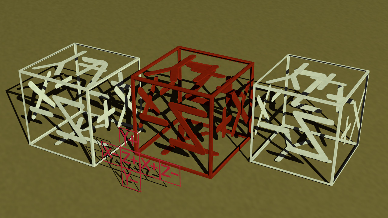
Yes and then the 0.5 offset to set the half width (radius for other map
types) during the warp - this last part has to do with how the warp{}
mapping works. The deep pink isosurface shape in the attached image more
or less shows the shape as it would exist at z=0.5 inside the unit cube
after that last translate.
>
>> warp{cubic} // Wrap pattern around origin.
>> warp{turbulence 0.04 octaves 5 omega 0.4 lambda 5} }
>> }
>
> I suppose it ought to be simple enough to write a macro that assembles such a
> map from a square, or add an internal function that does the same.
>
>
Yes, I think many ways possible to create the df3 plane(1) including
variations of the cubicMap.pov code attached earlier to this thread.
Your news post timing was good because I also need to make a correction
to the code snippet I posted.
The z passed to the pattern based function needs to be flipped to match
the in built in uv_maping for a box object and the warp{cubic} of an
image_map applied to box. These two more routine results being the left
and right white textured boxes in the attached image.
In other words where I had:
#declare Fn00 = function (x,y,z) { 0.025-(FnctTheDF3(x,y,z)) }
it needs to be:
#declare Fn00 = function (x,y,z) { 0.025-(FnctTheDF3(x,y,-z)) }
for the resultant isosurface (center box in the image) to match the two
other cubic maps. Off the top of my head, I'm unsure why the inversion
in z when used in the isosurface... I didn't notice the z-flip until I
tried my first non-symmetric map earlier today.
Bill P.
(1) - It need not be just one plane. We could create boxes within boxes
for example as one media/isosurface at the cost of the df3 getting
deeper/larger to do it.
Post a reply to this message
Attachments:
Download 'isoboxcubicmap.jpg' (212 KB)
Preview of image 'isoboxcubicmap.jpg'
|
|
| |
| |
|
|
|
|
| |
|
|